X beam introduction
The XY motion system (also known as the gantry module) controls the movement of the print head in the Factor 4. The print head is mounted on the X beam; it moves left and right along the X axis. The X beam itself is mounted on linear guide rails on both sides of the gantry's base plate and moves back and forth along the Y axis during printing, as well as during other operation, calibration, or maintenance actions.
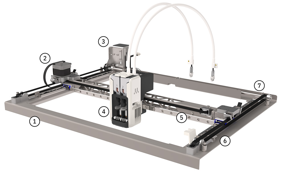 |
- Gantry base plate
- X motor
- Y motor
- Print head
- X beam
- Y tensioner and belt (right)
- Motion shaft with pulleys
|
For reliable motion and consistent print quality, the X beam must be perpendicular to the linear guide rails. Minor misalignments can typically be compensated for by the Factor 4's clever, built-in gantry calibration. However, if the misalignment (also known as X beam skew) is too severe, the printer may not be able to compensate. This can lead to print quality issues or more serious problems such as homing errors (e.g. ER303).
This article explains how to check for X beam skew and how to manually realign the beam if necessary.
Possible causes and how to prevent skew
The X beam could be pulled out of alignment for various reasons:
- Slack belts: If the belts in the gantry system are not tight, it is possible that a belt slips on one of the pulleys. This unequal belt tension can introduce skew. Ensure to check and reset the belt tension regularly.
- Loose belt wedges: This is related to the belt slack mentioned above. The belts in the XY motion system are open-ended, and each is secured with a small wedge. There are two wedges on each carriage (four in total for the Y belts). To prevent the Y belts from losing tension over time, the wedges should be firmly pressed down. First, loosen the screw in the Y tensioner to activate the spring. Then push down on each individual wedge to fully seat it. You can simply use your thumbs, or, if pressing with your thumbs is uncomfortable, you can use a blunt, non-damaging tool (such as the handle of a screwdriver) to assist. Do not use clamps, pliers, or any sharp or striking tools, as these may damage the component. A force of 80 N is recommended, but if a force gauge is not available, simply push down as hard as possible.
Note: This is only needed once (not a regular maintenance action), and is recommended for any Factor 4 printer in use since before August 2025, or after replacing the belts.
- Print head collisions: If the print head collides with an object during printing, the skipped steps can also cause the belt to slip on the pulley (especially in combination with slack belts). Ensure that there are no objects inside the build volume that could interfere with the printing process or block the print head movements. The print head may also collide with part of the print, for example, if it detached from the build plate or curled up due to warping. Please check the print settings and adhesion methods.
- Lift switch calibration: The lift switch at the side of the print head lifts and lowers the second print core during the leveling process and in dual-extrusion prints. For successful and reliable print core switching, it is important that the switch fits firmly in the switch bay. Failure to properly switch cores can cause collisions of the print head and lead to skew. Learn more about this calibration here: Factor 4 - Lift switch calibration
When to check for skew in the X beam
It is recommended to check for skew in the X beam in the following situations:
- ER303: This is a homing error, indicating that the print head is unable to move to its home position and/or that the optical limit switch cannot be activated correctly. The display will show which direction is affected. In case of a skewed beam, it is usually the Y limit switch that shows the error.
- ER306: This error is shown after running the gantry calibration, and the process has failed. There are multiple possible reasons why this calibration could have failed, so please make sure to run through all steps in the ER306 article, but always check for X beam skew.
- After shipping: Both the printer and the gantry modules are shipped in durable packaging, designed to protect the products during transit. However, particularly rough transport could cause unexpected issues, even if this is not directly noticeable from the outside of the packaging.
- Other XY motion problems: It is worth checking for X beam skew with any issue related to XY motion. This can include odd noises during print head movement, unexpected friction when (manually) moving the print head, or issues with storing the position of the purge location or lift switch.
How to check for skew in the X beam
Checking whether the X beam is properly aligned is straightforward once you know what to look for. A slight skew may not be visible when looking at the printer from a distance, so a hands-on check is required. To assess alignment accurately, you will need to manually move the X beam to the back of the gantry and inspect its position relative to the mechanical end stops on both sides. You will need a small mirror for better visibility; one is included in the Factor 4 Maintenance Kit.
End stops
In addition to the optical limit switches used for homing the print head, the gantry system includes fixed mechanical ‘end stops’: physical features of the gantry's base plate that prevent the linear bearings from sliding off the Y guide rails.
- Front end stops: On the front of the gantry's base plate, a small metal tab is located on each side, just before the end of the Y rails. The front tabs prevent the X beam from moving too far forward.
- Back end stops: At the back of the base plate, on each side, there is a small corner just beyond the end of the Y rails. When the X beam is moved all the way back, its sheet metal frame should touch these corners to stop further movement.
Note: Only the back end stops should be used for checking for skew and for the recalibration (if necessary).
Steps to check the calibration
Note: You can check X beam alignment while the printer is powered on, as long as it is idle. Make sure that the print head and X beam can move freely (no motor tension), that all components have cooled down, and that no print jobs can start unexpectedly (e.g. remotely via Digital Factory).
- Manually slide the print head to the left or right along the X beam, so that it is placed roughly in the middle of the X beam.
- With one hand on each side of the X beam, gently slide it towards the back until it can go no further and touches the back end stops.
Note: Do not apply force to only one side of the X beam. It is not recommended to push the print head; instead, push the carriages on either side above the Y belts.
- Hold a small mirror at a ± 45° angle above the right side of the gantry cover and X beam, so that you can see the small tab. Check whether the X beam is fully touching it.
- Next, hold the mirror above the left of the X beam to check that side.
If both sides of the X beam are making contact with their respective tabs, the beam appears well-aligned. If there is a gap on one side and a noticeable difference between left and right, the X beam is skewed. Proceed to the recalibration steps.
Tip: If you are unsure if the beam is skewed or require additional assistance with this process, please contact UltiMaker Support. Please share images of the X beam position.
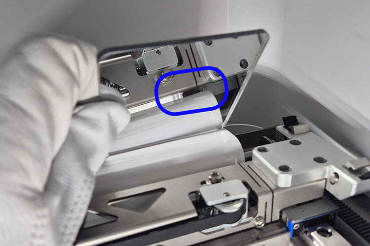 | 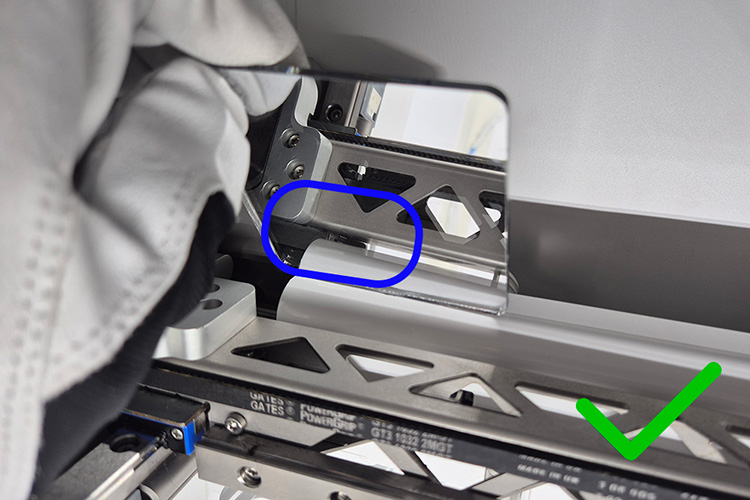 | 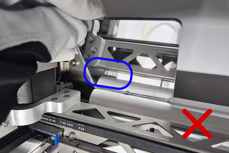 |
| Right side: The X beam is fully touching the corner at the back. | Left side: The X beam is fully touching the corner at the back. | Left side: There is a significant gap between the X beam and the corner at the back. Recalibration is needed. |
Maximum offsets
- If the right side of the X beam is fully touching, the maximum gap on the left is 0.5 mm.
A larger offset is likely to cause problems with homing the print head (ER303). - If the left side of the X beam is fully touching, the maximum gap on the right is 1 mm.
This side is less critical for homing errors, but larger offsets are likely to cause problems with the gantry calibration (ER306) or cause damage to the carriages.
How to manually recalibrate the X beam
To adjust the X beam position, you will need a Hex 2 mm screwdriver and a Torx 20 screwdriver. Both are included in the Factor 4 Maintenance Kit. You will have to loosen and retighten the Y tensioners (that hold the Y belts), and the pulley on the motion shaft in the back-right corner of the motion system.
Tip: It is possible to perform this calibration with the gantry system still inside the printer, although it can be easier to reach certain components (mainly the pulley at the back) if the XY motion module is removed from the printer first. You can find instructions on removing the gantry module here.
- Loosen the Y belts. Use the Torx 20 screwdriver to loosen the screws in the Y tensioners at the front of the gantry system. Firmly push each tensioner towards the back of the gantry to relieve the tension on the belts, and tighten the screws to keep the Y tensioners in place.
- Loosen the back-right pulley. This pulley has two set screws. Adjust the pulley's position so you can loosen each set screw, using the Hex 2 screwdriver.
- Move the X beam. With one hand on either side of the X beam, slowly push it all the way to the back of the gantry, making sure to apply equal pressure on both sides. Ensure the X beam is fully pressed against the corners at the back of the gantry system on both sides. A mirror can be used to check the alignment at the back, as described above.
- Reset the belt tension. While keeping the X beam firmly pushed against the back of the gantry, loosen and retighten the screws in the Y tensioners again to reset the belt tension.
- Secure the back-right pulley. Still keeping the X beam firmly in position, tighten one of the set screws of the pulley in the back right corner. Ensure that the pulley is pressed towards the left (against the spacer ring) before tightening it. If both set screws are accessible, tighten both. If only one can be reached, you can now move the X beam to the front (with one hand on either side) until the second set screw is accessible.
- Check the alignment again. Slowly move the X beam forward, then against the back again. Use the mirror to check that the X beam is now touching the corners on both sides. If there is still a gap or a noticeable difference between left and right, the calibration was not done successfully; please repeat the steps above.
Tip: Find the X beam calibration instructions in this step-by-step PDF guide or watch this demonstration video.
Post-adjustment calibrations
After performing this hardware adjustment, the following guided calibration procedures are recommended. All calibrations can be found in the Options menu (Gear icon):
- Lift switch calibration. Navigate to Maintenance → Print head → Calibrate lift switch (learn more here)
The switch bay in the front-right corner of the gantry enables the second print core to be lifted and lowered. This should be reset after adjusting the belts or making any gantry-related changes. It is important that this calibration is done first, as this affects the other two calibrations. - Gantry calibration. Navigate to Maintenance → Frame & motion → Calibrate gantry (learn more here)
This measures the new X beam offsets and applies the correct compensation for optimal reliability and dimensional accuracy. - Purge location. Navigate to Maintenance → Frame & motion → Calibrate purge location (learn more here)
This lets you accurately position the print head so that the nozzles are aligned with the holes in the purge rubbers. This ensures a reliable priming and wiping process.
Need further support?
If you have any questions about checking or adjusting the X beam, or you cannot manage to resolve the skew issue after following all the steps in this article, please contact support. Please include all relevant information, such as photos and videos (of the printer's behavior and/or the skew), any error messages you encounter, the printer's log files, and a clear description of the steps you have already taken to attempt to correct the problem.