The movements of the print head in the X and Y directions are controlled by the gantry. The UltiMaker Factor Series printers can run a gantry calibration procedure and perform some measurements to achieve optimal dimensional accuracy.
It is recommended to perform this calibration in the following situations:
- After replacing the gantry*
- After replacing the belts
- After calibrating the X beam
Tip: If the same gantry is reinstalled, without any adjustments to the long belts or the X beam, this calibration process is not necessary.
Preparation
Before starting this calibration, make sure that the printer is prepared.
Note: Before you run the gantry calibration procedure, ensure you have done the lift switch calibration first. The gantry calibration will fail if the print cores do not switch correctly.
Other preparations include:
- Print cores: Two print cores should be installed in the print head. This procedure requires at least a print core in slot 1 (left) of the print head. Make sure the nozzle cover bracket is securely closed.
- Nozzle tips: Make sure that the tips of the nozzles are clean. If there is material stuck to the outside of the nozzle, manually heat up the print core via the Configuration menu and remove the material with tweezers (learn more here).
- Flexible build plate: Remove the flexible build plate from the printer. Ensure that the build plate has cooled down to a safe temperature before reaching into the printer. The display will indicate with an orange status bar if the build plate is too hot (above 60 °C). The calibration process will ask you to confirm that the build plate is removed.
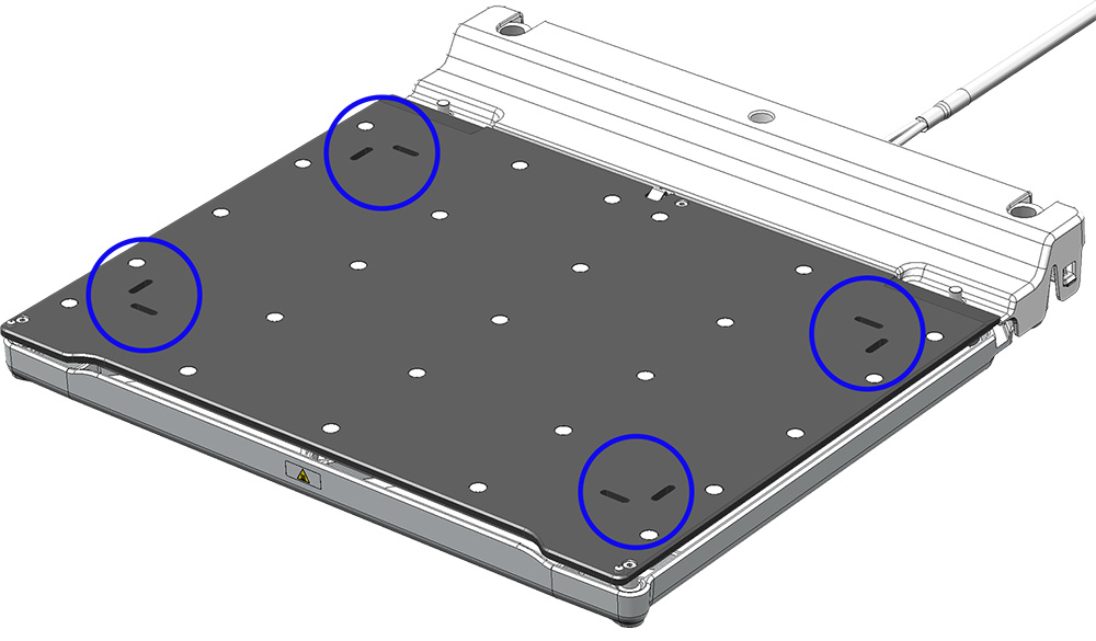
- Magnetic build plate: Ensure that the four sets of grooves in the black magnetic build plate (see image below) are clear from debris. If there is any dirt or filament residue in the grooves, clean them with tweezers, a cotton swab, or a (handheld) vacuum.
- Build chamber door: For the best results, keep the build chamber door closed during the calibration process. It is recommended to never open the door while the printer is in operation, unless you are specifically instructed to by the display or other (maintenance) instructions.
- Environment: Ensure that the UltiMaker Factor Series printer will not be affected by external sources of vibration. If multiple printers are installed on the same surface and these are in operation, either pause the print(s) or wait to perform the gantry calibration until the print jobs on any adjoining printers have finished. Do not touch or move the Factor Series printer during this calibration process.
Calibration process
After checking all the points listed above, start the calibration. In the Options menu (gear icon), navigate to Maintenance → Frame & motion → Calibrate gantry. Follow the steps on the display.
The printer will perform some measurements during this calibration. The print head and build plate start to move and the nozzle will follow the grooves in the build plate (see image). The process takes about 5 minutes.
Tip: This calibration is done automatically and does not require input from the user.
|  |
Results
After the process is complete, the display will indicate if this was successful or not. If the calibration is successful, the printer will store the calibration values and apply them during printing. This ensures that any skew in the gantry system is compensated for during motion.
If the display indicates that the calibration was not successful (ER306), this can be due to a number of factors. First check if all the print preparation steps listed above were followed correctly. If so, the gantry calibration may have failed because of:
- Exceeded skew: If the skew in the X or Y direction exceeds the threshold values, the printer can no longer compensate for this during printing. The most common cause for this is a skewed X beam.
- Build plate leveling: If the build plate leveling does not work or detects values outside of the tolerance range, the gantry calibration cannot be completed. Test the noise level of the inductive leveling sensor in the print head, or run a leveling test to check the skew. Visit this article for additional troubleshooting tips.
- Print core switching: If nozzle switching does not work correctly, build plate leveling will also fail. If the switch on the right side of the print head misses the switch bay during the switching procedure, its position must be recalibrated. Run the lift switch calibration via the Maintenance menu.
- Homing errors: If the printer cannot accurately determine its home position, the other measurements will be unreliable. Check that the optical limit switches are free from objects or debris, which could trigger the switch unexpectedly, and make sure that no obstructions are preventing the print head from reaching the switches.
Note: For more information on resolving failed calibration issues, visit the ER306 support article. Homing errors will show the relevant error messages instead of ER306. Scan the QR code on the display or navigate to the indicated error page for more information.