This error can occur on the UltiMaker Factor 4. It indicates a problem with movement in the X, Y, or Z direction during a homing command. The display will indicate which direction is affected.
Note: In previous firmware, the optical limit switch errors were numbered incorrectly. This was fixed in firmware 10.1.0.
If you see ER305 on the display of your printer with the title "Optical switch engaged error", please visit the ER304 page instead and update the firmware to the latest version.
Affected system
The Factor 4 gantry module contains the X and Y motors for horizontal movement, while the Z motor with its long lead screw controls the movements along the vertical axis. All axes have an optical limit switch, which help to determine the home position.
Issue
If this error appears, Factor 4 did not detect a correct homing signal in the expected timeframe, neither from motor stall detection nor from the optical switch. Without the ability to home, the printer cannot be used. It is possible that there was no movement at all along the indicated axis.
Possible root causes include a defective or disconnected motor, or loose components such as belts and/or pulleys in the gantry system (for X and Y). See the detailed troubleshooting steps per root cause below.
Troubleshooting
If ER305 appears, the printer requires a restart before further steps can be taken. Reboot the printer via the button on the display.
Observe homing behavior
First, try the homing command again. Carefully observe what happens following the home command to help determine the root cause.
For X and Y, manually move the print head to the front-right corner. This is the opposite side of the limit switches. In the Settings menu, navigate to Maintenance → Print head → Home print head. Observe if the motors are correctly engaged and if the print head and X beam move at all.
- If neither motor is moving, the motor cable at the back of the gantry may be disconnected. See the instructions below.
- If only one of the motors is unresponsive, the cable at the motors may be disconnected.
- If the motors are spinning, but the print head is not moving in the X or Y direction (or moving erratically), the belts may be slipping or the pulleys are loose.
For Z, check if the Z motor still moves when activated. Manually lift up the build plate, then use the Move build plate → Lower option in the Maintenance menu. Let go of the build plate just before selecting this option. Although the build plate will lower by itself due to gravity, you should be able to hear the Z motor if it is engaged. If there is no response from the motor, it may be disconnected. See the instructions below.
Note: Make sure to keep hands clear of the build volume after using the Move build plate option.
Check the belts and pulleys
If you observed that the X and Y motors were responsive, but the movement of the print head was not accurate, the belts and/or pulleys in the gantry might be loose. Follow the steps below to resolve the issue.
Tip: If the X and/or Y motors were not responsive during the homing command, or if the Z direction was affected, skip this section. Follow the instructions under Check the motor connections.
To adjust the belts and pulleys, the gantry must be removed from the printer. You can find the instructions here. Place the gantry on a flat, stable surface.
Check the belts
Ensure that the belts have proper tension. Check that the tension indicators are secured and that the indicator lines are within tolerance. If the belts feel very slack, loosen the tensioners so that the position will automatically be adjusted, then retighten them. For additional instructions, visit this page.
Check the pulleys
Ensure that all pulleys are securely tightened. In particular, check the pulleys connected to the motors. For the Y direction, also check the pulleys on the motion shaft at the back. If any of the pulleys are loose, use a Hex 2 screwdriver to tighten the set screws.
Tip: After adjusting the pulleys, ensure that you have not introduced skew in the X beam. If necessary, manually calibrate the X beam.
Check the motor connections
If you observed no motion at all in one or more directions, the motors might be defective or disconnected. Follow the steps below to check the connections.
| Gantry X/Y cable |
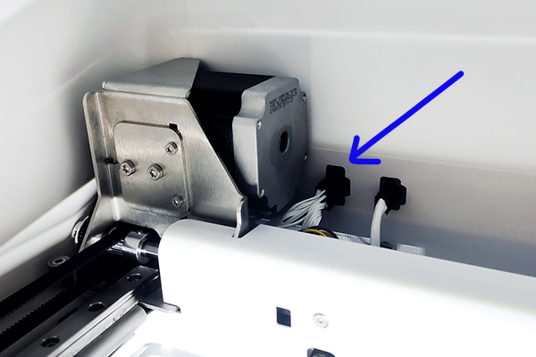
Both X and Y motors are connected via a single cable. This should be connected to the port at the back of the gantry system, right next to the Y motor. The motor cable is the one on the left. Check if this is securely connected and reconnect it, if necessary.
Tip: If this connector is too hard to reach, loosen the captive screws that secure the gantry module and slide the gantry a few cm forward.
|
|
|---|
| X motor cable |
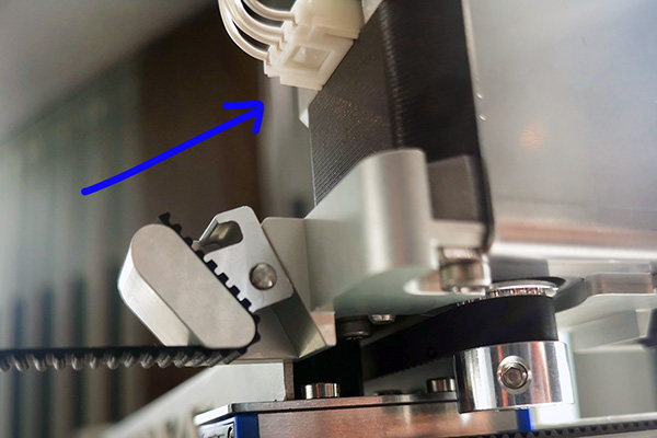
To reach the cable connected directly to the X motor, the gantry system must be removed from the printer. You can find the instructions here.
The X motor connector is at the back of the motor. Check if this is securely connected and reconnect it, if necessary. Also inspect the cable for damage.
|
|
|---|
| Y motor cable |
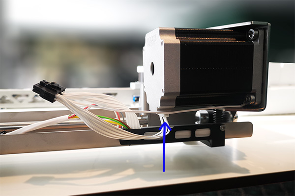
To reach the cable connected directly to the Y motor, the gantry system must be removed from the printer. You can find the instructions here.
The Y motor connector is at the bottom of the motor, you can reach it from the back of the gantry. Check if this is securely connected and reconnect it, if necessary. Also inspect the cable for damage.
|
|
|---|
| Electronics XY |
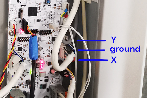
The gantry motors are connected to the mainboard. To access this, the back cover panel must be removed*.
The X and Y motors are connected on the right side of the board (as seen from the back). Ensure these cables are connected properly, and reconnect them, if necessary.
|
|
|---|
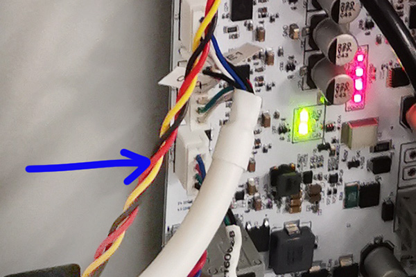
| Electronics Z |
The Z motor is connected to the mainboard. To access this, the back cover panel must be removed*.
The cable of the Z motor connects on the left side of the board (as seen from the back). Ensure it is connected properly, and reconnect it, if necessary.
|
|
|---|
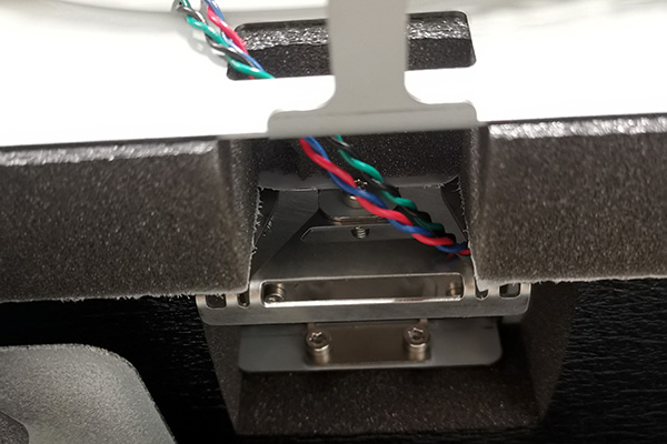
| Z motor cable |
The cable on the Z motor is on the right side, as seen from the back. However, accessing the connector is difficult and requires some disassembly. Please contact support or your local reseller for additional information.
|
|
|---|
Note: It is recommended to contact support or your local reseller before removing the back panel. Turn off the printer and disconnect the power cable. Take ESD measures when handling the electronics. Always check if you are allowed to access the electronics according to local and/or company regulations.
Need further support?
If the information provided on this page has not helped to resolve the issue or you require additional assistance, please contact support. When submitting a support case, ensure you have your printer's serial number ready. Note the error code and the steps already taken. Additionally, save your log files and share them with support.