Product notification
This product has been discontinued, and its end-of-service date has passed. While it is no longer supported, the information on this page is still available for your reference.
|
This article guides you through all the steps necessary to correctly install the hardware accessories that come with the UltiMaker 3 or 3 Extended. A few items should be installed before powering on the printer for the first time.
Spool holder
The spool holder has an NFC reader to automatically detect which UltiMaker materials are installed on the printer. To benefit from this feature, the spool holder must be connected to the electronics. Installing and connecting the spool holder can be done in a few easy steps:
1. Insert the spool holder
Gently place the printer on its left side. Take the spool holder and insert the top part into the hole in the back panel. Push the spool holder towards the bottom of the printer until it snaps into place.
2. Connect the NFC cable
Connect the NFC cable to the NFC socket at the bottom of the printer. The flat side of the connector faces away from the bottom panel. When the connector is secure, guide the cable through the notch in the back panel.
Note: For the UltiMaker 3 Extended, the cable is exactly long enough, but for the UltiMaker 3, it is too long. The excess cable should be coiled against the back panel. This will allow the cable cover to fit properly in the next step.
3. Place the cable cover
Place the metal cable cover over the cable, with the top part against the spool holder. Then gently push it against the back panel until the tabs snap into place.
You can now place the UltiMaker 3 upright again.
Tip: The filament guide of the spool holder will not be used yet; you will install this while loading materials.
Glass plate
The glass plate is the print surface of your UltiMaker 3 (Extended).
To install the glass build plate, open up the two build plate clamps at the front. Slide the glass plate onto the build plate until it fits into the clamps at the back. Close the clamps at the front to secure the glass plate.
Glass plate tips:
- Place the glass build plate with the warning icon facing up. This side is best for adhesion.
- Most materials benefit from a thin layer of glue applied to the glass plate. This improves adhesion and can also serve as a protective layer for the glass to prevent chipping.
- Always hold the glass plate flat when installing it or removing it from the build plate.
Caution: Leaving the build plate clamps open may damage your UltiMaker 3 when the build plate is raised.
Power supply
The final step of the installation is connecting the power supply. First, make sure that the switch at the back of the UltiMaker 3 is in the Off position.
- Connect your country-specific power cable to the adapter.
- Connect the plug to a wall socket.
- Connect the other side of the cable to the socket at the back of the UltiMaker 3. Make sure that the flat side of the cable is facing down. Pull back the slider of the connector, insert it into the printer, and let go to secure the cable.
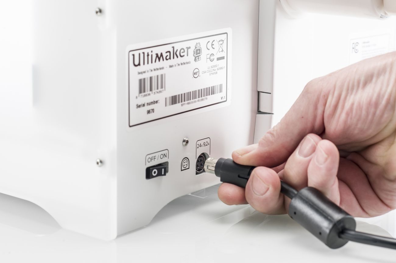
Caution: A mains socket with protective earth/ground terminal must be used. Make sure that the building installation has dedicated means of over-current and short-circuit protection.
All the hardware accessories are now installed. You can turn the UltiMaker 3 or UltiMaker 3 Extended on for the first time and proceed with the welcome setup. This includes loading print cores and materials, setting up a network connection, and leveling the build plate.