This article describes the various support settings in UltiMaker Cura. These settings are available when opening the Custom mode.
Some 3D models require support structures to be printed properly. UltiMaker and other FDM 3D printers work by placing layers of molten material on top of each other. A limitation of this technology is that each layer must be supported by the previous one. Although printers can handle overhangs and bridges, a layer simply cannot start in mid-air. For this, you can print support structures under your model. These support structures can be removed when the print is finished.
Tip: Some support settings can be chosen in the Recommended print settings overview (enable, type, and placement). Other settings are altered in the Custom view.
Generate Support
To allow the generation of support structures, enable the setting Generate Support. Based on the other settings (see below), support structures will automatically generate where required.
Note: If support is not enabled, the underlying support settings will not be visible in Cura.
Support Extruder
Dual extrusion machines allow printing with multiple colors or materials. This can be very useful to dedicate one extruder for printing support structures, for example, with water-soluble (PVA) or Breakaway material. Cura lets you choose with which extruder you want to print the support structures, and you can even select an extruder for specific parts of the support structures:
- Support Infill Extruder
- First Layer Support Extruder
- Support Interface Extruder
- Support Roof Extruder
- Support Floor Extruder
Note: The Support Extruder setting and underlying options are only visible when the machine has multiple extruders, and the second extruder must be enabled in Cura.
|
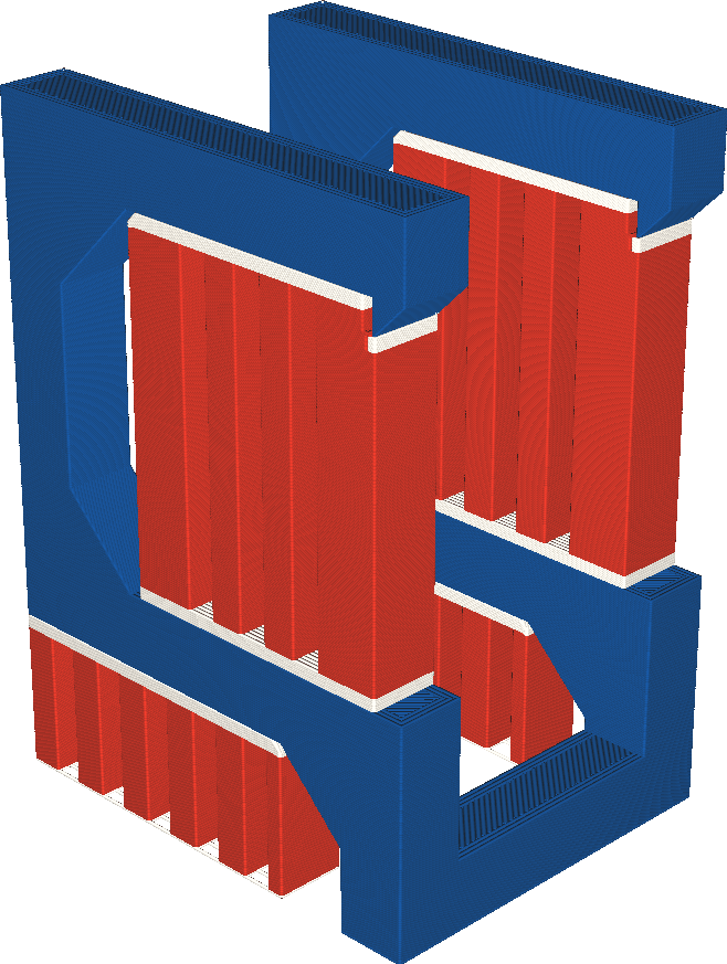
The support infill extruder is indicated in red.
|

The first layer support extruder is indicated in red.
|
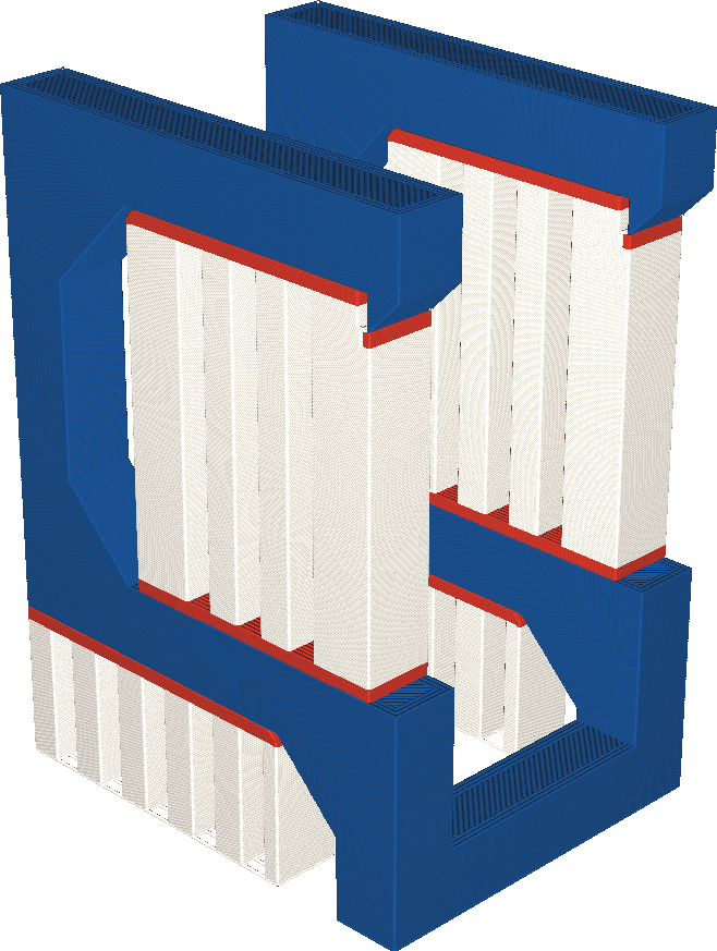
The support interface extruder is indicated in red.
|
Support Structure
UltiMaker Cura offers two techniques to generate support: Normal and Tree. Both of these structure types have their own advantages and disadvantages.
Normal support generates a straight structure underneath the areas of the model that need support. This is quite sturdy and has large contact areas, to offer maximum support. However, this can cause more scarring on the model (unless a soluble support material is used). This technique uses a lot of material and takes a long time to print.
As an alternative, Tree support creates branches that grow around your 3D model. The benefits of this alternative include reduced print time and less scarring of the model. However, due to its complex structure, it takes significantly longer to slice and it is not suitable for all materials.
Tip: For underlying settings for the Tree support type, see below.
The model on the left has Normal support and the model on the right has Tree support.
Tree Support settings
When Tree is chosen as the support structure, several settings become available. The Tree type creates hollow branches Instead of printing supports up in straight lines from the build plate, we can use tree support to print tree-like structures that support models. These supports are hollow and can be designed to follow different angles. The following parameters control the way the supports grow.
- Maximum Branch Angle: The maximum overhang angle the branches may use to print sideways. An overhang angle of 40° is considered reliable.
- Branch Diameter: The diameter of the branch where it touches the model. Wide branches are stable yet hard to remove, thin branches are less stable yet easy to remove.
- Trunk Diameter: This is the diameter at the start of the tree support, which is its widest point. Higher values mean sturdier support, but this will take up more space and take longer to print.
- Branch Diameter Angle: With this setting, you control the growth rate of the branches. A bigger angle increases the branch's bottom width.
- Preferred Branch Angle: The angle if the branches do not have to avoid the model. Lower values mean a more vertical and more stable growth, while higher values allow faster merging.
- Diameter Increase To Model: The most the diameter of a branch that has to connect to the model may increase by merging with branches that could reach the build plate.
- Minimum Height To Model: If a branch is placed on the model, it must be at least this tall. This setting prevents small blobs of support, which are likely to fail.
- Initial Layer Diameter: Every branch tries to reach this diameter when reaching the build plate, if allowed by other settings. This improves build plate adhesion.
- Branch Density: Adjusts the density of the support structure used to generate the tips of the branches. Higher values result in better overhangs, but the structures may be harder to remove.
- Tip Diameter: The diameter of the very tip of the branches.
- Limit Branch Reach: When enabled, this limits how far each branch should travel from the point it supports. This makes the support more sturdy, but may generate more branches and increase printing time and material usage.
- Optimal Branch Range: A recommendation on how far branches can travel from the points they support. Lower values make for sturdier support, but increase printing time and material usage.
- Rest Preference: The preferred placement of support structures, including on the build plate or resting on the model. This is only a preference, and supports may still be placed on the model if the locations cannot be reached otherwise.
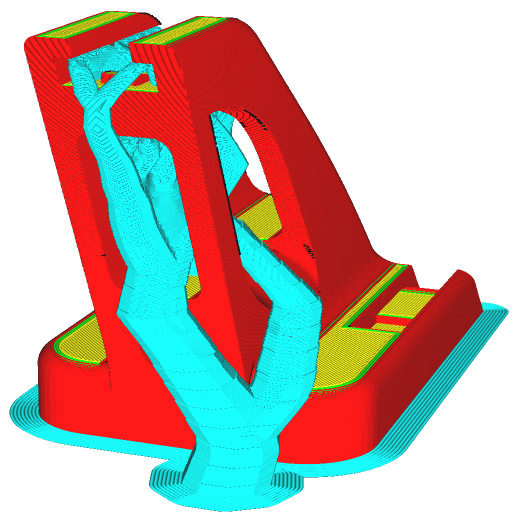
This model has been sliced with the default tree support parameters.
Support Placement
This setting defines where the support structure is printed. It contains the following options:
- Touching build plate: Support material is only printed from the build plate up.
- Everywhere: Support material is printed below every part that needs support, which means that it can also be placed on or inside a model.
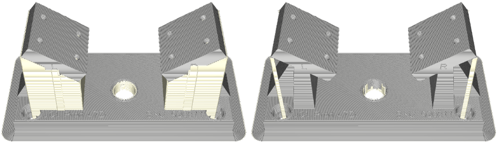
This model has parts with overhangs. The model on the left has support everywhere, while the model on the right has support on the build plate only.
Note: Printing supports on a model can cause scarring on the model (unless a soluble support material is used). However, note that when limiting support to touching build plate only can lead to unstable or insufficient support structures.
Support Overhang Angle
The overhang angle influences how much support material is added and where. A smaller angle leads to more support. For example, at a value of 0° all overhangs are supported, while at 90° no support material is added.
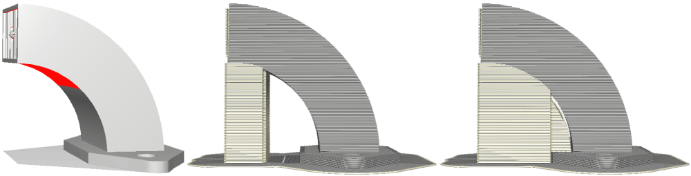
The image on the left is a model shown in the solid mode. The red areas indicate the overhang area that needs support. The model in the middle has an overhang angle of 70°, while the model on the right has an overhang angle of 45°
Support Pattern
There are different patterns available for printing support structures, resulting in sturdy or easy-to-remove support. Different models, materials, or applications may benefit from different support patterns. You can choose from the patterns below:
- Lines: Only straight lines, not perpendicular to the model. This is the easiest to remove but tends to be very unstable.
- Grid: A pattern of straight lines, perpendicular to each other. This creates a very sturdy block, but it is quite difficult to remove.
- Triangles: A pattern of straight lines at 60° angles. It is the sturdiest of support structures but does not give good overhang quality.
- Concentric: A pattern of evenly spaced concentric rings. This is very easy to remove, but may not always support all walls and can sometimes be suspended in the air.
- ZigZag: Similar to lines, but the ends are connected. This is easy to remove, leaves a good quality, and prints fast and reliably due to no retractions or travel moves.
- Cross: Creates a fractional pattern with cross-like shapes. This is easy to flex and remove from the model but takes longer to print due to the intricate shapes.
- Gyroid. A wavy pattern of curved lines that varies across layers. This is especially recommended for soluble support structures as this structure does not create air pockets, allowing for faster dissolving times.

Support Wall Line Count
The support wall is a perimeter printed around the support pattern. This wall adds strength to the outer parts of the support structure to improve reliability, mainly used for printing PVA material. When printing supports with the build material, removal of support is more important, and no extra support wall is used.
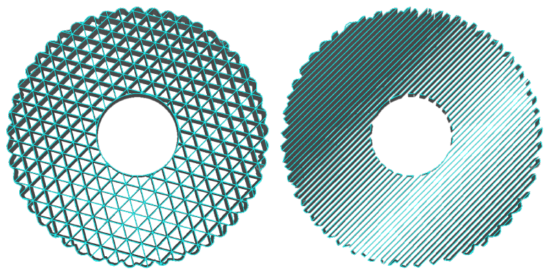
The model on the left has supports printed with PVA, it requires a support wall. The model on the right is printed with the build material, it does not have a wall to ease the post-processing.
Connect Support Lines / ZigZags
With some support structure types, the supports can be quite unstable if thin strips are generated. With this setting enabled, the endpoints of the support structures will be connected. This can add more material but increases the reliability of the structures and prints with a more even flow rate.
Support Density
This defines the density of support structures. A higher value will lead to stronger support and better overhang quality, but these will be more difficult to remove and take more time to print.
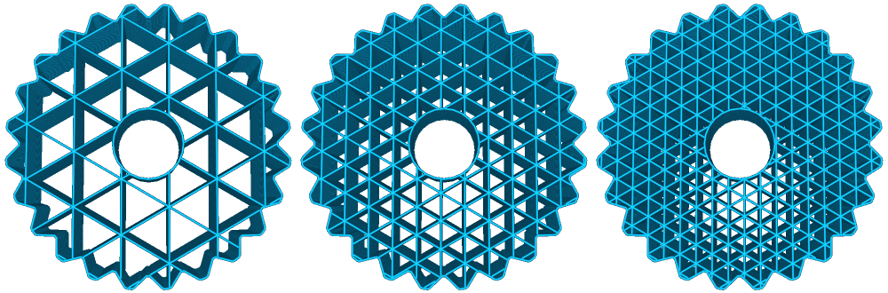
This model has triangle support with three different densities: 15 %, 30 % and 45 %.
Note: For many profiles, the support infill density is quite high. This is because the setting Gradual Support Infill Steps is enabled. The Support Density shows the infill density for the final layers under the model. Learn more about using gradual infill steps below.
Support line distance
The support line distance is a child setting of the support density; instead of calculating it as a percentage, it allows you to set the distance between supports directly. This setting can be adjusted separately for the initial layer.
Support Infill Line Directions
Normally, the supports will be generated at 0° and 90° angles, whereas the top and bottom layers of the model are usually angled at 45°. This prevents support structures from bonding too strongly with the model.
Certain models may benefit from alternative support structure angles. This setting lets you choose rotation angles for the support pattern. Enter this in between the square brackets, for example [45], to offset with a 45° angle.
Tip: You can also enter multiple angles, separated by commas. Cura will then alternate between the angles over the layers.
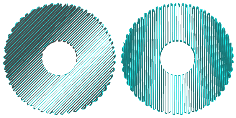
The support structure on the left is offset by 45° while the structure on the right uses the standard angle.
Support Brim
The support brim adds a number of concentric layers on the inside of the support structure on the initial layer, similar to the model brim. It improves the adhesion of the support material to the build plate, and thereby its reliability.
Tip: You can set the support brim either as a width in mm, or choose a number of brim lines.
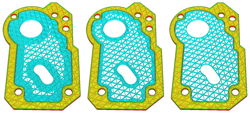
The model on the left has a large 8 mm support brim, the model in the middle has it set to 3 mm, and the model on the right has this setting disabled.
Support Z Distance
This refers to the distance from the top and bottom of the support structure relative to the model. This setting is divided into the top distance and bottom distance. The top distance defines the distance between the top of the support and the bottom of the model, and the bottom distance refers to the distance between the bottom of the support and the top part of the model.

A small distance between the support structure and parts of the model is necessary in order to remove the supports easily after the model has been printed. A low value creates a smoother surface, but can also make it more difficult to remove the support properly. When printing with build material supports, a distance of 2 layer heights is usually recommended.
Tip: When printing with multiple extruders and using soluble support materials, this can be set to 0 mm. This allows for the best adhesion of the support to the model and vice versa, and no distance is required to remove the support structure after printing as this will be dissolved.
Support X/Y Distance
This setting adjusts the distance between the support structure and the model in the X and Y directions. A higher value reduces the chance of the support structure hitting the model. However, this also creates a larger distance between the model and support structure, which may result in smaller overhangs not being fully supported.
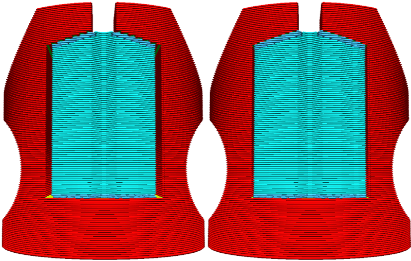
The model on the left has a support X/Y distance of 0.7 mm, while the one on the right has a 0.3 mm distance.
Support Distance Priority
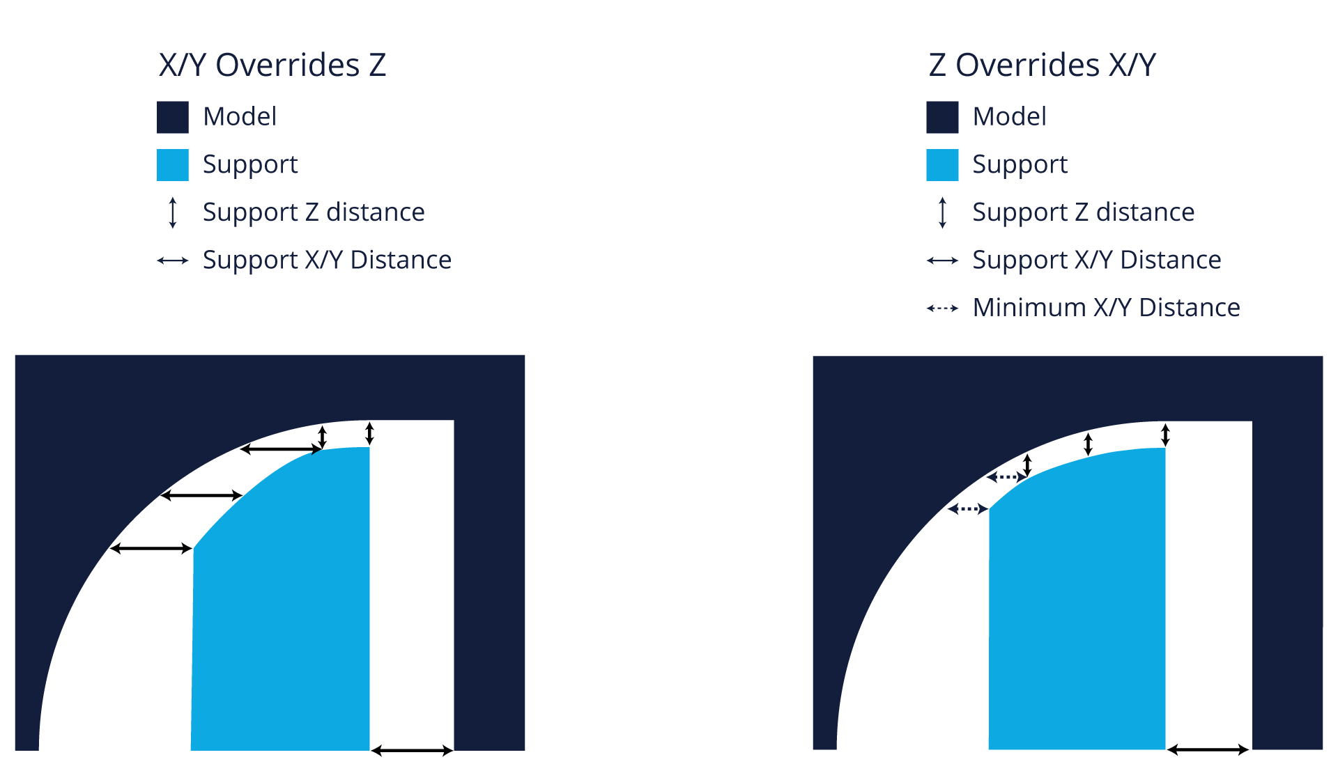
The settings for Z distance and XY distance are usually different. When generating support structures, UltiMaker Cura cannot follow both of these rules. The Support Distance Priority setting defines which of the two is more important, XY or Z. When XY is chosen, the horizontal distance between the model and the support structure is kept constant, but this can create a larger Z distance. When Z takes priority, this (vertical) is the constant distance and the supports may be closer to the model in the XY direction than specified.
The image below shows the priority when X/Y overrides Z, and when Z override X/Y.
Minimum Support X/Y Distance
When the Z overrides the X/Y distance priority, as discussed above, the X/Y distance may force the support to hit the model. To ensure that this does not happen, Cura will respect the minimum support X/Y distance at all times.
Support Stair Step Height
When support placement type Everywhere is selected, support structures can be generated on top of the model. This structure does not necessarily follow the contours of the model smoothly. Instead, the bottom of the support structure consists of small stair-like steps. Changing the stair step height value affects how big these steps should be. A low value will result in a smoother bottom of the support and more connections between the model and support structure. A higher value makes it easier to remove the support afterward.
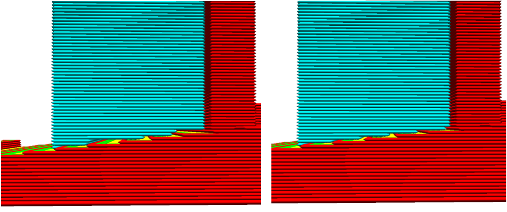 The object on the left has a high value for the stair step height, and the model on the right has a lower value.
When this setting is > 0.0 mm, two additional settings become available:
- Support Stair Step Maximum Width: This determines the maximum width of the stair steps. The support structure normally follows the model with the given stair step height value. However, if that exceeds the maximum width setting, it then follows the model's surface for the rest of that step.
- Support Stair Step Minimum Slope Angle: On shallow slopes, the stair steps at the bottom can be very wide, increasing the need for bridging. This setting controls the minimum slope angle for which to apply stair steps. Higher values lead to sturdier support, but these structures can be harder to remove. Lower values reduce scarring and are easier to remove, but may cause unstable support structures.
Support Join Distance
Very thin support structures are best avoided, as they can easily fall or cause extrusion issues. With this setting, you control the maximum distance between separate support structures in the X/Y directions. When supports are closer together than this value, they will merge. Using a high value for this setting will cause support structures to merge sooner.
Merging support structures leads to more stable support and, depending on the pattern, will often reduce printing time and material usage. However, increasing this value too much could create a big block of unnecessary support which uses more material and can be harder to remove.
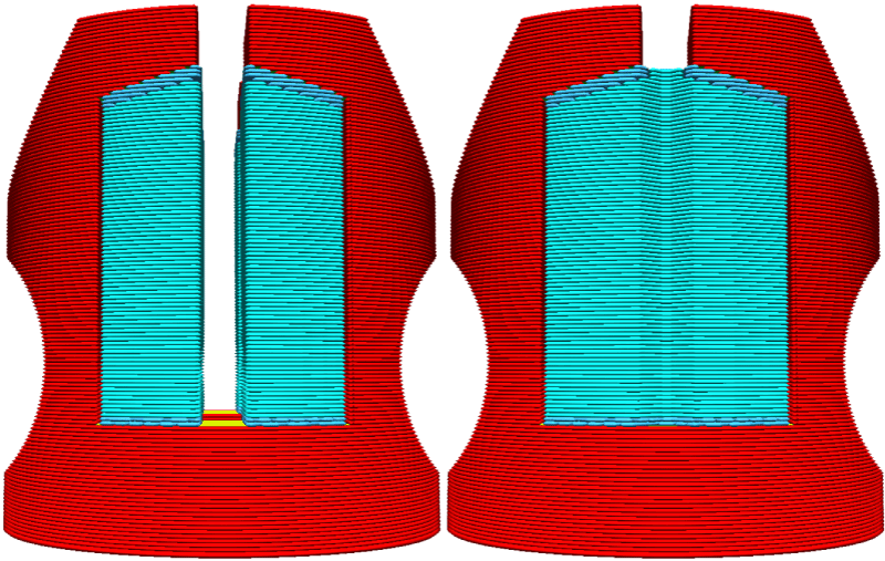
The model on the left has separate supports, while the support join distance value of the right model causes the supports to merge.
Support Horizontal Expansion
An offset can be applied to support structures in the X and Y directions. Positive values for Support Horizontal Expansion make the support structures slightly wider than the model. This results in sturdier support (also in combination with Support Join Distance). Additionally, this helps to prevent very thin support pillars and to ensure that the minimum support area is met. This is especially beneficial for materials that are hard to extrude, such as PVA.
Reducing this setting often means less material is required. Choosing a negative value makes the support smaller than the model and may be beneficial to remove very thin support structures.
Note: Negative horizontal expansion values may lead to surface quality issues. To remove thin pieces of support, you can also use the Minimum Support Area setting, or apply a support blocker.
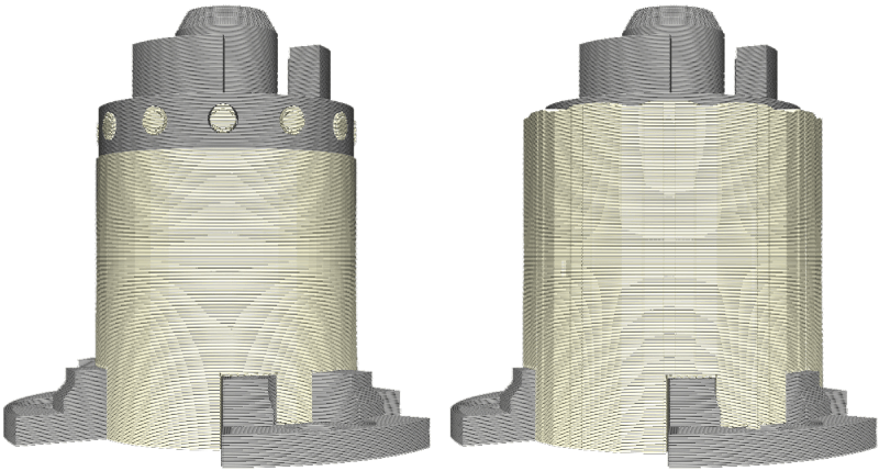
The model on the left has horizontal expansion disabled which saves material and decreases print time. When using PVA, the small support areas at the top may experience flow issues. The model on the right has horizontal expansion enabled, which increases the strength of the structure and improves the flow.
Support Infill Layer Thickness
You can use thicker layers to print the support infill than the model. The visual quality of the support infill is not important, so choosing a higher value can decrease printing time. Always use a multiple of the layer height in the profile. If the chosen setting is not an exact multiple, Cura will round this automatically.
Note: Changing this setting only affects the support infill structure. The walls, roofs, and bottoms will be printed with the default layer height.

The model on the left has a support infill layer thickness of 0.1 mm (same as the profile setting) and the model on the right has a double thickness of 0.2 mm. Note that in the layer view, these lines look as if they are much wider, but they are actually thicker. When you go through the layer view, you will notice that the support infill will be skipped on alternating layers when this is double the layer height.
Gradual Support Infill Steps and Step Height
Gradual support works similarly to gradual infill. Each gradual infill step divides the infill density by two, resulting in a lighter infill at the bottom and a dense infill towards the top. Gradual infill improves support cost and efficiency without the impairment of visual quality.
The Infill Steps setting controls the number of steps with which to divide the infill density. The Infill Step Height determines the height of each of the steps. Both settings work in combination with the general Support Infill Density.
For example, if the infill density is set to 80%, the number of infill steps is 2, and the step height is 1 mm, then the support directly below the model will be printed with 80% infill. Between 1 mm and 2 mm below the model, the infill density is reduced to 40%. The support structures more than 2 mm below the model will be printed with a 20% infill density.
Tip: Using infill steps will cause some parts of the support structure to be printed in the air. However, using a sufficient step height ensures that the layers will repair themselves before the next support infill step. Gradual supports work best with at least one wall around the support structure. This prevents sagging of the outer parts of the infill steps and increases stability.
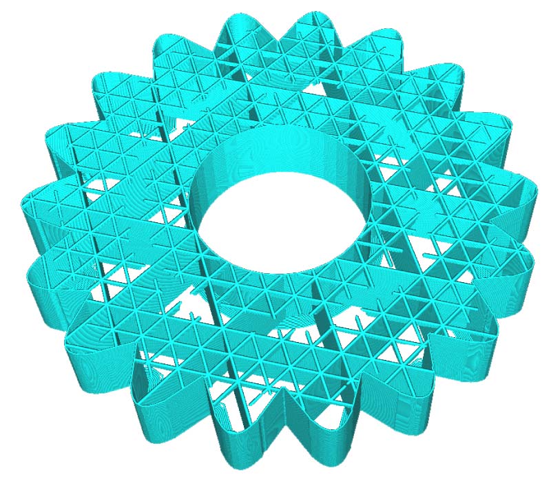
This model is printed with two gradual infill steps of 1 mm each. The preview mode shows that the supports get denser 1 mm and 2 mm below model surfaces.
Minimum Support Area
This setting defines the minimum footprint area supports need to cover, before being ignored. By default, all areas in need of support are printed. When thin support structures occur in unwanted places, they can be filtered out. Thin support structures tend to be unstable and are best avoided. However, with this setting enabled, some parts of the model may not be supported at all and the model will have a decreased overhang quality.
Tip: To prevent thin support pillars, you can also apply Support Horizontal Expansion or Join Distance to increase the support area, or use support blockers to remove unnecessary thin parts of support.
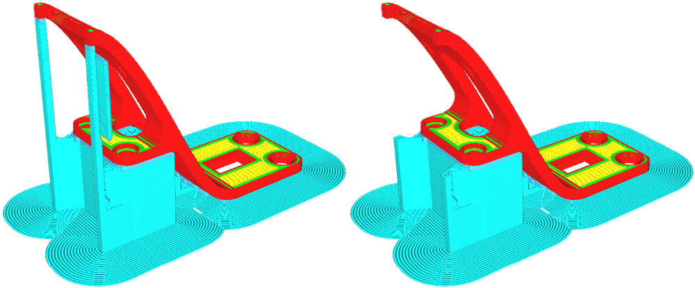
The model on the left has all supports in place, as is the default. The model on the right has a minimum support area of 3 mm2, ignoring the thin overhang areas.
Enable Support Interface
A support interface generates a dense skin on the roof and floor of the support structure. Doing this supports the bottom layer of the print better, leading to a more even surface. It is important to remember that a support roof is more difficult to remove than regular support, so post-processing may require more work, specifically when using non-soluble supports.
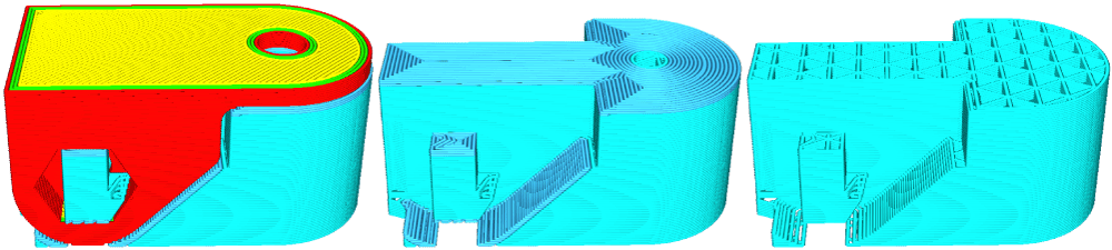
This model is sliced in two different ways: the example in the middle has the support interface enabled, while the right example has the support interface disabled.
The support roofs and floors can be set separately and each has its own options:
- Support Interface Thickness: The thickness of the support interface(s). This must be a multiple of the layer height, or will automatically be rounded. Thicker interfaces have better quality, but take more time and can be harder to remove.
- Support Interface Resolution: The resolution checked in the Z direction, which determines where support interface is printed. Setting this to a higher value than the layer height speeds up slicing, but can cause unexpected issues with interface generation, especially for very thin models.
- Support Interface Density / Line Distance: The density of interface of the support structure. This can be set as a percentage, or overruled with a line distance in mm. Denser interfaces lead to a higher model surface quality, but will be much harder to remove as the contact area is increased (especially for non-soluble support materials).
- Support Interface Pattern: The pattern that determines how the interfaces are printed, similar to the top and bottom layers of a model. This can be different from the rest of the support structure. At higher densities, it is recommended to use Concentric or ZigZag rather than Triangles, for example.
- Minimum Support Interface Area: Support interfaces smaller than this area will not be generated, but regular support will be used. This prevents extruding small bits of material.
- Support Interface Horizontal Expansion: This setting makes the interface bigger in the X and Y directions. This creates better support for the edges of the model, can make the interface a little easier to remove, and improves the flow (when the interface is printed with a hard-to-extrude material). Note that this setting cannot exceed the Support Horizontal Expansion.
- Support Interface Line Directions: Normally, the interface will be printed perpendicular to the model to prevent bonding. You can customize the angles for the support interface, similar to Support Interface Line Directions.
Fan Speed Override
When enabled, the print cooling fan speed is altered for the skin layer directly above the support. A higher fan speed cools down the bottom layer of the model more, which prevents it from bonding too much with the support structure and makes the supports easier to remove.
Use Towers
By enabling this setting, support structures are printed as towers that reinforce tiny overhang areas. Support towers are only printed for support areas that are smaller than the set minimum diameter. All support areas larger than this value will use regular support.
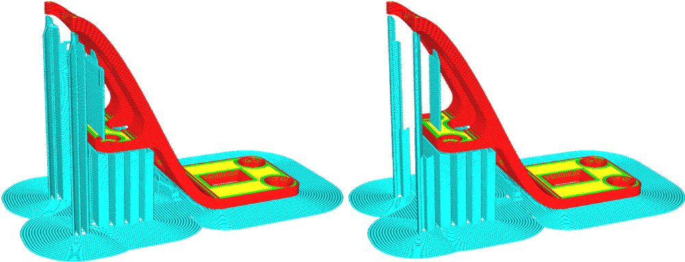
The model on the left has the default value of Use Towers enabled. The model on the right has the setting disabled.
Support towers have several underlying settings to alter the characteristics of the generated towers:
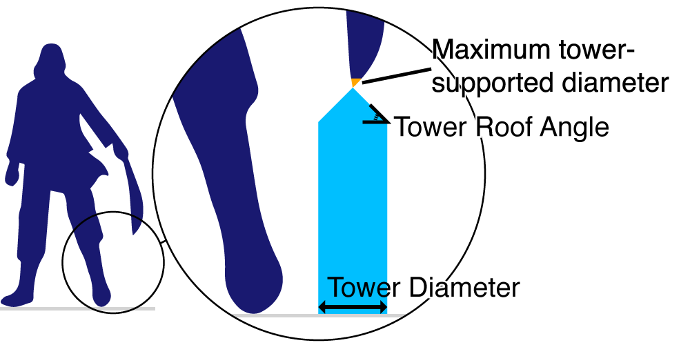
- Tower Diameter: How wide the bottom of the towers must be under small support areas.
- Maximum Tower-Supported Diameter: If the support area is smaller than this value, a tower will be generated. If it is larger, normal supports will be used.
- Tower Roof Angle: The towers are wider at the bottom than at the top. This setting controls the steepness of the angle. Lower values generate a flatter roof (more stable, but takes more material), while higher values generate a pointy tip (less stable, but takes less material).
The image below illustrates how the changes of each setting affect the tower.
Tip: Continue learning about all UltiMaker Cura custom settings. The next section is Build plate adhesion.