This article describes the various infill settings in UltiMaker Cura. These settings are available when opening the Custom mode.
Tip: Some infill settings can be chosen in the Recommended print settings overview (density and pattern). Other settings are altered in the Custom view.
Infill refers to the internal structure of a printed object, which is filled with a pattern or mesh to provide strength and stability while minimizing material use. The infill percentage and pattern can be adjusted to achieve a balance between strength, weight, and print time. A higher infill percentage results in a denser, stronger print, while a lower percentage makes the object lighter but potentially less durable. Infill patterns, such as grid, cubic, or gyroid, influence not only the strength and flexibility of the final print but also how efficiently the object is produced. Understanding and optimizing infill settings is crucial for achieving the desired mechanical properties and material efficiency in 3D printed objects.
Note: All settings in the Infill category are described here. Not all settings may be visible due to dependencies on other settings. The information in this article is subject to change, as new Cura releases may change, add, or remove settings.
Infill Extruder
If your printer supports printing with multiple extruders, you can select with which extruder you want to print the infill material. Use a different material to change the mechanical properties of your object, or use a bigger nozzle size for the infill pattern to increase the printing speed and strength without decreasing the visual quality.
Tip: Infill settings are not shared between extruders. If you change the infill extruder, ensure to select the correct extruder tab in the Custom mode if you want to make changes.
Infill Density
Tip: This setting can be adjusted from the Recommended mode.
This setting configures the density of the volume inside the print, which is a major factor in the strength of the final print as well as the top surface quality. The higher the infill density, the closer the infill lines are placed together.
Increasing the infill density has a big effect on your print and printing strategy:
- Pro: The print will be stronger.
- Pro: The top surfaces will be supported better, making the model smoother and more watertight.
- Con: The print will require more material, also increasing the cost and weight of the object.
- Con: The print will take more time to complete.
Note that different infill patterns (see below) benefit from different infill densities. If you want to print your object close to or completely solid (Infill Density = 80-100%), it is best to select a pattern with straight lines, such as Lines or Zigzag, or other non-overlapping shapes such as Concentric.
Tip: After slicing, always check the Preview mode to ensure that your chosen infill density works well for your model and all surfaces are correctly supported.
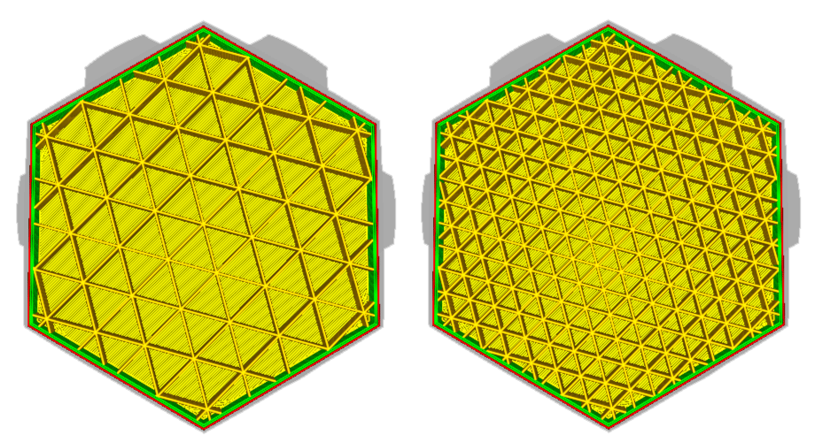
Image above: The model on the right has a higher infill density than the model on the left.
Infill Line Distance
This is a subsetting of Infill Density. Instead of setting the infill density as a percentage, it is also possible to set the line distance. This determines the distance between each infill line, which has the same effect as changing the infill density. A larger distance between the lines lowers the density.
Normally, the infill line distance is computed based on the selected density and line width. This setting is always leading. When the Infill Line Distance setting is changed manually, the Infill Density setting becomes grayed-out.
Infill Pattern
Tip: This setting can be adjusted from the Recommended mode.
UltiMaker Cura allows you to change the pattern of the printed infill structure. Various patterns are available, each with its own benefits. Some can be used for most objects, while others are developed for very specific applications. Select the pattern (and density), which best serves your model and application.
 |  |  |
Honeycomb
Type: 2D infill
Good for: Engineering applications
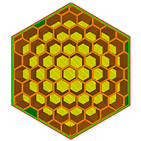
One of the most requested infill types, available since Cura 5.12. This was implemented as a strong pattern for functional 3D prints, but without self-intersections. This is the new default pattern in many UltiMaker profiles, especially for engineering intents.
|
Octagon
Type: 2D infill
Good for: Engineering applications
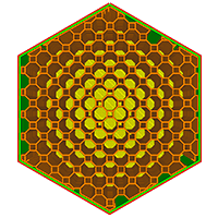
Octagon, like the Honeycomb pattern, was added to offer a strong, but non-intersecting alternative to, for example, Triangles. This reduces vibrations and Z resonance, especially on high-speed printers. Octagon is available since Cura 5.12.
|
Lines
Type: 2D infill
Good for: Visual models
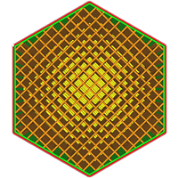
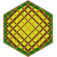
This pattern creates parallel lines. By default, the lines alternate their direction perpendicularly from layer to layer. This infill is weak, but the lines are printed close together without costing a lot of material, enabling excellent top surface support.
|
 |  |  |
ZigZag
Type: 2D infill
Good for: Visual models
This pattern, like Lines, creates parallel lines on alternating layers. The lines are connected, preventing flow interruptions. This infill is weak, but the lines are printed close together without costing a lot of material, enabling excellent top surface support.
|
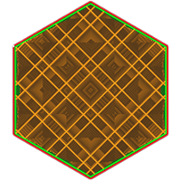
Grid*
Type: 2D infill
Good for: General applications
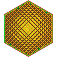
The grid infill pattern creates two perpendicular sets of lines. Together this forms a pattern of squares. This is a very strong pattern in the vertical direction and offers great top surface support.
|
Triangles*
Type: 2D infill
Good for: General applications
This pattern consists of three lines in different directions, creating triangle pockets. This offers equal horizontal strength in each direction, but needs more top layers to get an even surface. The intersections cause flow interruptions, making this pattern unsuitable for higher densities.
|
 |  |  |
Concentric
Type: 2D infill
Good for: Flexible models
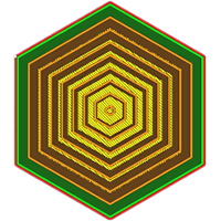
This pattern creates rings parallel to the walls of the object. It supports top surfaces, but offers no strength in the horizontal direction. It is very suitable for flexible materials and objects that should bend. When printed at 100% infill, this pattern is actually the strongest.
|
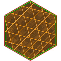
Tri-hexagon*
Type: 2D infill
Good for: General applications
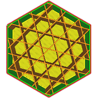
This pattern consists of three lines in different directions, but offset so they don't all intersect at the same point. This is the strongest pattern horizontally, with equal strength in every direction. This pattern requires more top layers to get an even surface.
|
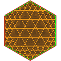
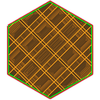
Octet
Type: 3D infill
Good for: Engineering applications
The octet pattern creates a combination of regular tetrahedra and cubes. Every so often, multiple infill lines will be placed adjacent to each other. This creates a strong internal frame that quickly dissipates load. This pattern has reduced pillowing, but needs many top layers due to long bridging distances.
|
 |  |  |
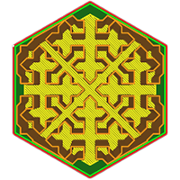
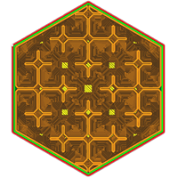
Cubic
Type: 3D infill
Good for: Visual and engineering applications
This pattern creates 3-dimensional cubes, standing on a corner. This offers good strength, equal in all directions. A benefit is a reduced pillowing effect, as this does not produce long pockets of air.
|
Cubic Subdivision
Type: 3D infill
Good for: Visual and engineering applications, material saving
This pattern creates 3-dimensional cubes, standing on a corner. Towards the center, the cubes are bigger to save on material. This offers a great balance between strength, visual quality, and material usage. The pattern is more complex, so it may take longer to slice.
|
Quarter Cubic
Type: 3D infill
Good for: Engineering applications
The quarter cubic pattern creates a 3-dimensional tessellation consisting of tetrahedra and truncated tetrahedra. Like the Octet infill pattern, it creates an internal frame to which loads can be dissipated. The quarter cubic pattern is especially suitable for thin functional parts.
|
 |  |  |
Cross
Type: 2D infill
Good for: Flexible models
The cross infill pattern produces a space-filling curve along the inside of the volume. It is great for flexible objects, as it requires no retractions and is evenly squishy in all horizontal directions. The print will be stronger in the horizontal direction.
|
Cross 3D
Type: 3D infill
Good for: Flexible models
This infill pattern produces a space-filling curve along the inside of the volume, and pulses along the Z axis in order to make it weaker in the vertical direction. This will be almost equally squishy in all directions, making this the most suitable for flexible parts.
|
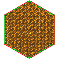
Gyroid
Type: 3D infill
Good for: Flexible models
The gyroid infill pattern produces a wavy pattern that alternates directions. It is equally strong in all directions, but not very stiff. This makes it useful for flexible materials, but prints will be harder than with Cross (3D) infill. The gyroid pattern looks very interesting, so is also favored for its looks. Note that this can take very long to slice and produces large gcode files.
|
|
| |
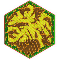
Lightning
Type: 3D infill
Good for: Material saving
The lightning infill produces a jagged, minimal pattern that only supports the top surface. It builds up and branches out like a lightning bolt. This saves a lot of material, but does not add any strength and may be unstable in larger volumes.
|
| |
Note: The 2D infill patterns Triangles, Grid, and Tri-Hexagon (and to a lesser degree, 3D patterns like Cubic and Octet) have self-intersecting lines. Because the nozzle crosses over printed paths on the same layer, this can cause material buildup, nozzle collisions, and build plate vibrations. Use these patterns with caution and avoid them altogether on the UltiMaker S6, S8, and Factor Series to prevent damage to the printer.
Connect Infill Lines
This setting connects the endpoints of the infill pattern, where the infill meets the inner wall or skin, using a line that follows the edge of the infill area. This reduces the amount of retractions as it converts the infill pattern into as few individual lines as possible. A major benefit of this is a more constant flow rate, which improves print quality and strength of the infill structure. Overall model strength is also improved when this setting is enabled, as it prints extra material along the walls, which also helps to make the infill adhere better. The downside is that it takes longer and more material to print.
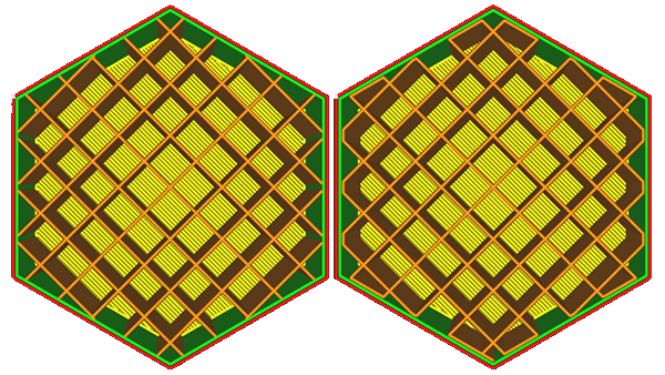
Image above: The model on the left uses Grid infill with Connect Infill Lines disabled; the model on the right has this setting enabled.
Connect Infill Polygons
When the infill consists of closed loops, these closed loops can be fused together to form one single loop. Enabling this setting will make small connections where polygons are adjacent.
This setting is only available when the infill consists of loops that are adjacent to each other. That means that either:
- The infill pattern is set to Cross or Cross 3D.
- The infill lines are multiplied to an even number (see Infill Line Multiplier below).
- There are at least 2 extra walls around the infill (see Extra Infill Wall Count below).
The aim of this function is to prevent travel moves. The final line will be one single loop for every connected part of infill, so there will not be any travel moves. This makes it easier to work with flexible filaments, because those are harder to retract and work best if they can keep flowing through the nozzle.
Connecting these loops can also make the infill stronger by enhancing the connection between the loops internally. However, this may introduce a lot of 180° turns, which may weaken the connections. This setting's impact on strength depends on how the loops mesh out through the shape of your model.
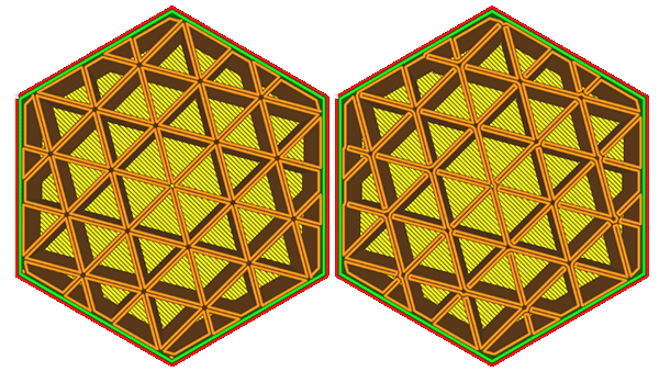
Image above: The model on the left has two-lined Triangle infill; the infill lines are isolated shapes. The model on the right has Connect Infill Polygons enabled; the infill forms a continuous line.
Infill Line Directions
Infill patterns have predetermined line angles. For example, with square patterns such as Lines, ZigZag, or Grid, the infill lines print at a 45° angle. At this angle, both the X and Y motors work together to obtain maximum acceleration and jerk on the layer without losing quality. You can customize the direction of the infill line to increase strength, optimize acceleration, or for visual effects.
To change the direction, enter your desired value(s) between the brackets. If you want multiple angles, separate them with a comma. For example: [0,45]. The angles will be alternated per layer.
Tip: When selecting angles for your line directions, note that 0° is parallel with the Y axis and 90° is parellel with the X axis.
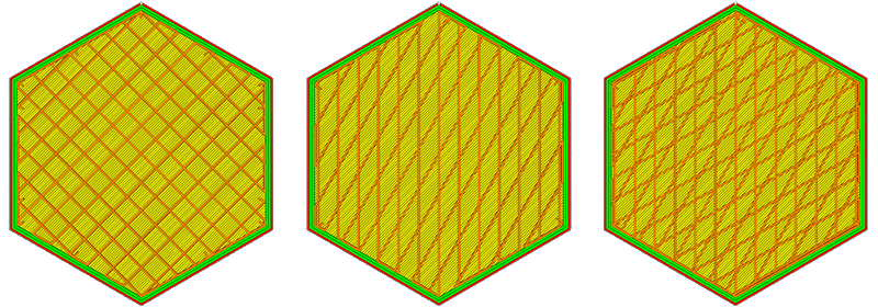
Image above: This example shows ZigZag infill. The model on the left has default values. The middle one has custom values [0,30]. For the right model, a third angle was added: [0,30,60].
Infill XY Offset
Infill patterns are normally centered for each 3D model. You can apply an offset for the X and/or Y direction to control where the infill will be placed. Especially for lower infill densities, this setting can be useful to position infill lines exactly where they are needed. As seen above, a positive value moves the infill pattern UP and RIGHT, while a negative value moves it DOWN or LEFT.
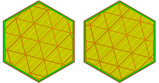
Image above: The models above have Triangle infill. For the model on the left, the XY offset is default, and the pattern is centered. The model on the right has a 5 mm offset in both X and Y; you can see that the pattern has shifted to the right and up.
Note: This does not work for all infill types. Certain patterns, such as Honeycomb and Octagon, have a predetermined layout on the build plate. Other patterns, such as Concentric and Cubic Subdivision, will always work towards the model center. The setting will not be visible for incompatible infill patterns.
Infill Line Multiplier
By increasing this setting, Cura will place more infill lines directly next to the other infill lines. This effectively increases the infill density beyond what the Infill Density setting specifies, but instead of spacing the infill lines out evenly, the lines are placed directly adjacent to each other.
Increasing the number of fill lines will increase the strength of the infill structure, because the lines lean on each other for extra rigidity. This creates an overall stronger printed part. The downsides of using this setting are that the print will take longer and use more material to print, and the infill can show more through the outer surface.
Tip: If the multiplier is set to an even value, the option Connect Infill Polygons becomes available.
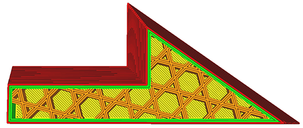
Image above: The model shown above has an infill multiplier value of 3.
Extra Infill Wall Count
This setting adds a number of contours around the infill areas. This is similar to increasing the number of walls or adding an extra skin wall, but the contours will be placed around the infill structure. These walls are printed with the infill settings.
Adding one or more infill walls greatly increases the strength of the model and reduces the visibility of infill through the skin, but also increases printing time and material usage.
Tip: It is a good idea to add at least one extra wall around either the infill or the skin, because it prevents the skin lines from ending in mid-air.
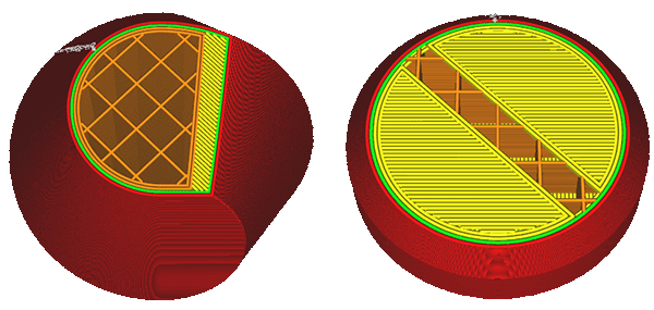
Image above: The model on the left has two extra walls around the infill structure. For comparison, the model on the right has two extra walls around the skin.
Infill Overlap
With this setting, you can control the amount of overlap between the infill and walls. It can be set as a percentage (of the line width of the infill) or as a value in mm, and it affects the overlap between the infill lines and the innermost wall.
A higher value usually results in better bonding between the infill and walls, making the part stronger. However, it might also reduce the visual quality of the print, because the infill could show through the outer walls. This results in a pattern on the outer surface of the print.
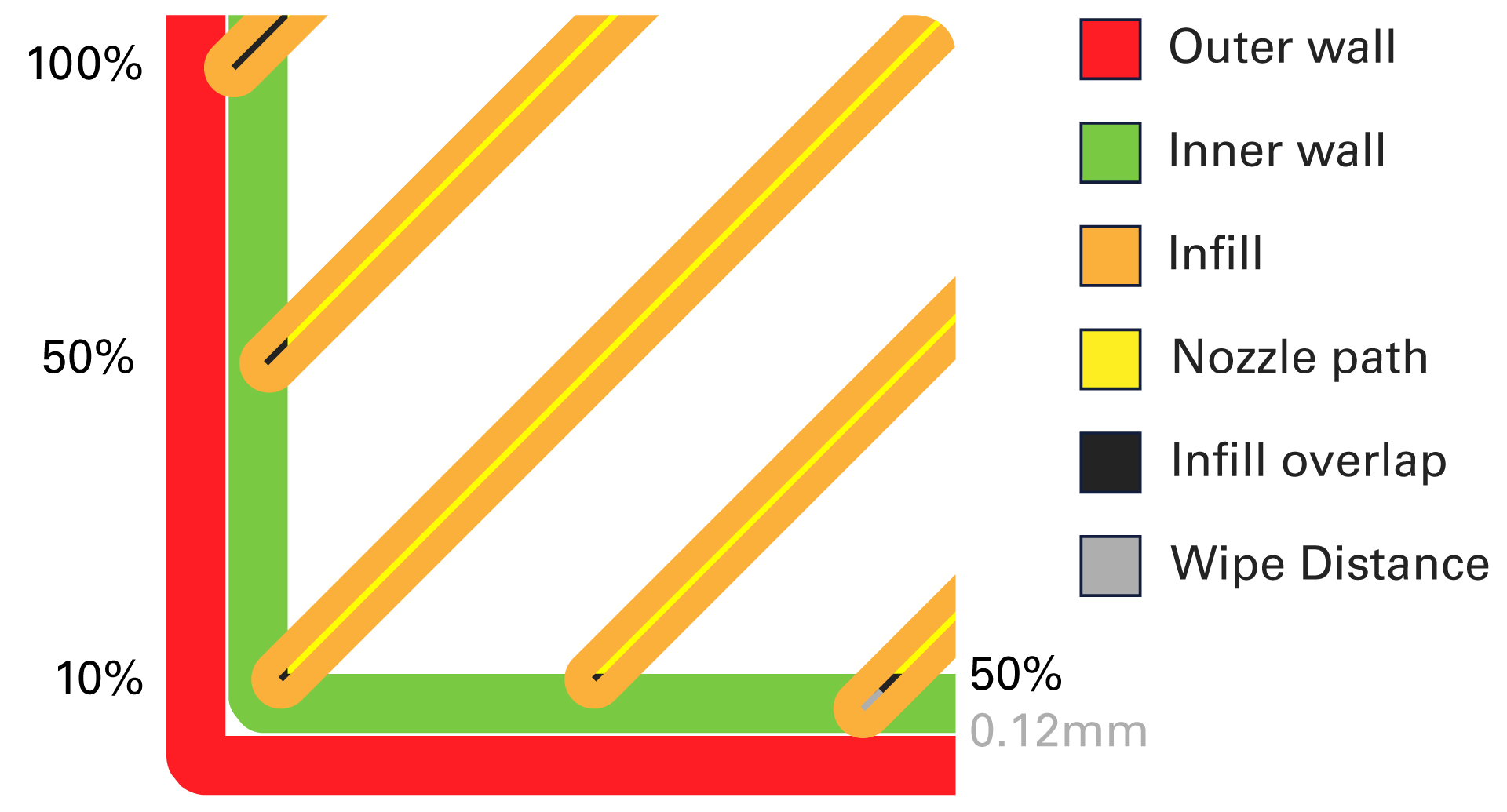
Image above: A visualization of the infill overlap and wipe distance.
Infill Wipe Distance
This setting will make the nozzle move a little bit further than the end of the infill line with a small travel move. The aim of this small travel move is to wipe off the material onto the wall next to it. This fuses the infill line to the wall better. See the image above for a visualization.
While this travel move makes the object stronger, the main disadvantage is that this travel move goes through the wall, which leaves a visible mark on the outside of the print. This strengthens the effect of the infill being visible on the outer surface of the objects.
Note: This setting only applies to the ends of the infill lines. When using connected infill lines, there will be much fewer ends.
Infill Layer Thickness
Since the layer height of the infill is not important for visual quality, you can use thicker layers on the infill to reduce the print time. This setting causes layers of infill to be combined together, as long as there are multiple layers of infill directly above each other. It will then not print any infill on some of the layers, but in the highest of the combined layers it will extrude more material to make up for it. For example, when your layer height is 0.1 mm and the infill is 0.2 mm, the printer will first print two layers of walls (and skin and/or supports, if applicable), and then it will print one thicker infill layer.
In layer view, it will look as if the infill lines have become much wider. When actually printed, the infill lines will drop down further instead of spreading out horizontally.
The Infill Layer Thickness must always be a multiple of the normal layer height. If a different value is selected, Cura will round off to the closest multiple.
Note: If the difference between the Layer Height and Infill Layer Height is too big, this requires a big change in material flow when switching to and from printing the infill. This could cause some under and over-extrusion issues in these places.
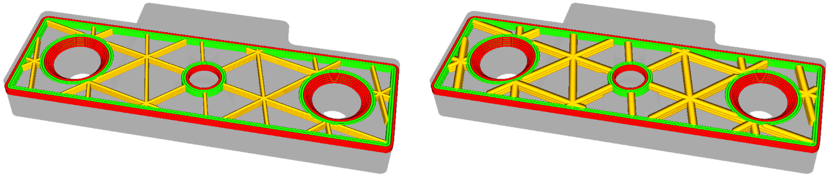
Image above: The model on the left has equal layer heights throughout, and the model on the right has an Infill Layer Height of twice the normal Layer Height.
Gradual Infill Steps
Gradual infill reduces the amount of infill used by decreasing the infill density in the lower layers. This saves printing time and material usage, while still offering a dense support below any top surfaces. Note that this will decrease the strength of the infill structure and the object, and should be used for visual models only.
This setting indicates in how many steps the infill density is reduced. At every step, the infill density is halved. For example, starting with an infill percentage of 20% and two gradual infill steps, the infill density of the lower parts will be 10% and 5%, respectively.
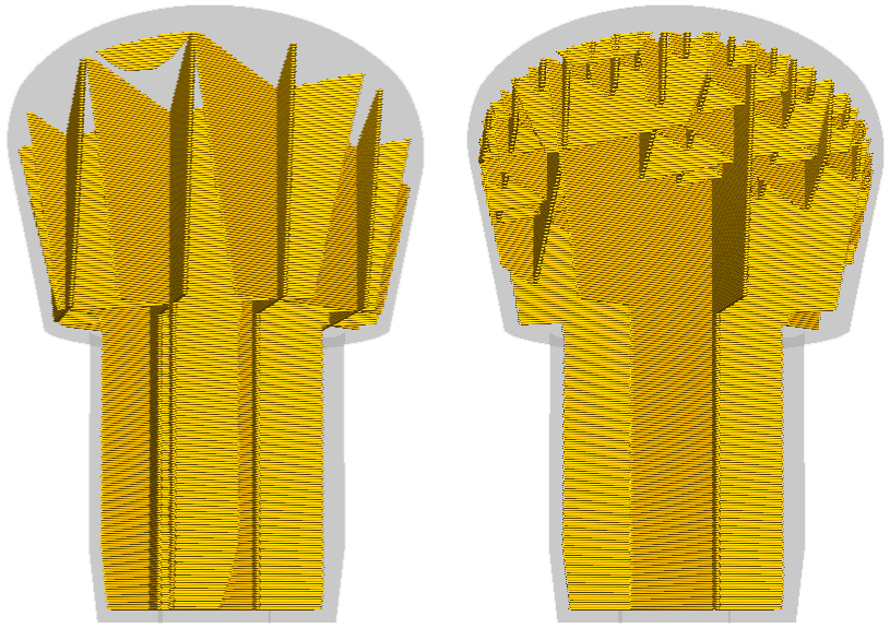
Image above: The model on the left has normal infill, and the model on the right uses Gradual Infill Steps.
Gradual Infill Step Height
This setting controls the height of each of the gradual infill steps. It is only visible if Gradual Infill Steps is set to 1 or higher.
The gradual steps are calculated from the top down. After reaching the height specified in this setting, the infill will be halved. For example, let's say you are printing an object with the following settings:
- Layer Height / Infill Layer Height = 0.15 mm
- Infill Density = 40%
- Gradual Infill Steps = 2
- Gradual Infill Step Height = 1.5 mm
Then, just below the top surface, the infill will be printed at 40% density for 10 layers. During the next 10 layers, the infill will have 20% density. For the rest of the print (below), the infill density will be 10%.
Especially after large density transitions, it is normal that some infill layers will not be supported and will print in mid-air. These first layers will only attach to the sides of the print and the previously printed infill structure. Since the visual quality of the infill is not important, this usually does not cause any problems. This will take a few layers to get better. You can increase the step height to give the infill structure more chance to repair itself before the next transition or before printing the top surfaces, but this will take more material.
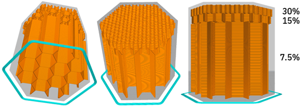
Image above: Another example and visualization of gradual infill steps. This model has an Infill Density of 30%, 2 Gradual Infill Steps, and a Step Height of 5 mm.
Infill Before Walls
This setting affects the order in which different parts of the model are printed. If this setting is enabled, the infill will be printed before the walls. When disabled, the walls will be printed first. Both options have their benefits and downsides, and which is best depends on your application. It is mostly a trade-off between accuracy and strength:
- Disabled (walls first): If the walls are printed before the infill, the walls could have nothing to attach to, causing them to sag more. However, the walls will have solidified first and will not be pushed away by the infill, which prevents the infill from shining through the walls.
- Enabled (infill first): If the infill is printed before the walls, the walls will get pushed away where infill is attached to the walls, which makes the walls less accurate and can cause the infill to shine through the surface, creating a pattern visible on the outside. However, the infill will hold the walls in place better while they are printed, leading to better overhangs.
Minimum Infill Area
This setting allows small areas on a single layer to be printed with skin instead of infill, to make them fully solid. This is especially useful on models with thin pieces that require more strength, without increasing the overall infill density or using cutting meshes. An added benefit is that this setting prevents printing very short infill lines, which could cause flow disruptions.
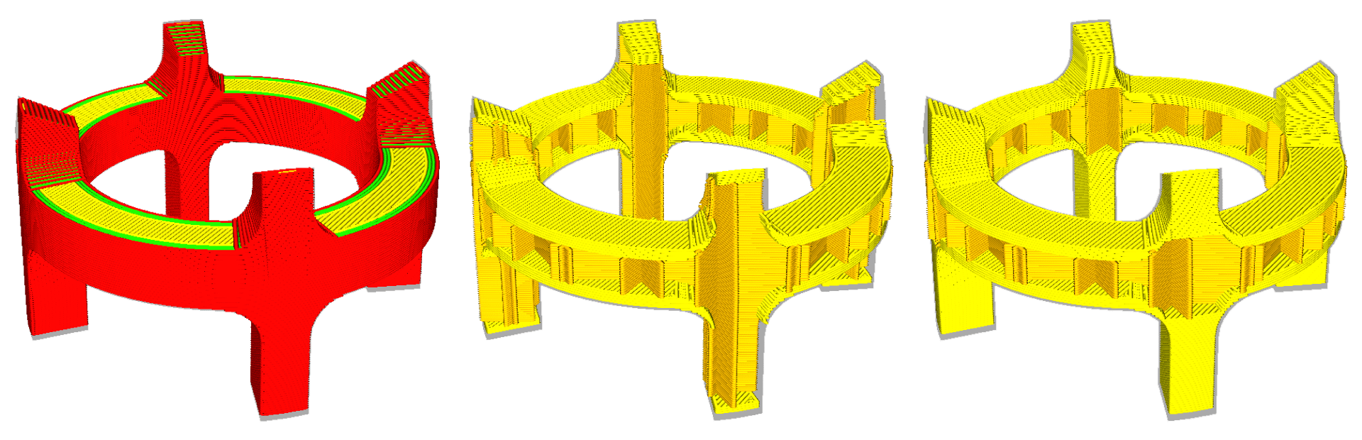
Image above: This coupler has thin pieces. The image in the middle has normal infill (Minimum Infill Area = 0), which leaves some open areas. The image on the right uses a Minimum Infill Area to strengthen the legs of this coupler by filling them completely with skin.
Infill Support
When enabled, this treats infill as support. Infill will then only generate where it is needed in order to support the top surface. It behaves as if the model is hollow and generates support inside it, but this support is generated using the infill settings. See the image below for a visualization.
For some models, this saves a lot of material with little impact on the visual quality. However, the strength of the object is greatly reduced. Especially if there are steep slopes in the model, there will often be no infill behind the walls. This setting should be used for visual models only.
Infill Overhang Angle
If Infill Support is enabled, you can set an overhang angle, similar to the support overhang settings. This setting is not visible if infill support is disabled.
This determines the minimum overhang angle of the surface that needs to be supported with infill. Increasing this angle will cause the infill to support less of the top surface. This saves on printing time and material, but will cause the top skin to sag a bit more.
- A value of 0° will act like normal infill. It supports everything.
- A value of 90° will remove all infill material.
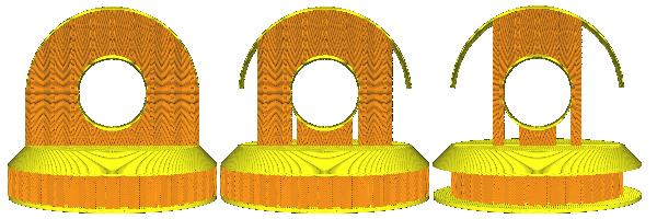
Image above: This shows the differences between infill support settings. The model on the left has Infill Support disabled; the entire object is full of infill. The model in the middle has Infill Support enabled with a low/medium setting for Infill Overhang Angle; only the very steep angles are not supported with infill. The model on the right has a high value for Infill Overhang Angle; only the almost horizontal surfaces are supported with infill.
Infill Skin Support
If this setting is enabled, Cura will generate a solid pattern just below a skin layer. This prevents the skin from printing in the air. This is especially useful for lower infill densities and models with very steep overhanging or flat top surfaces.
The Skin Support ensures that the solid layers always have an anchor point. This means the start and end of each Infill Skin Support line segment is attached to a wall, skin, or infill line segment and never starts or finishes in mid-air. The skin layer above the solid infill will therefore have a sturdy and even base.
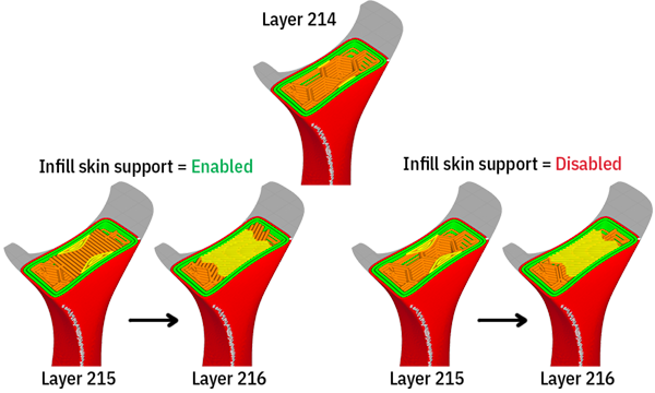
Image above: The top image shows the layer view, just before the top skin will be placed. On the left, Infill Skin Support is enabled, and a solid infill layer supports the skin. On the right, this setting is not enabled and some of the skin lines start or end in mid-air.
Note: This setting was introduced in 5.12 to consolidate and replace previous settings, including Skin Edge Support Thickness / Layers, Extra Infill Lines to Support Skin, and Bridging Over Infill.
Several options for the skin support can be configured, if this setting is enabled:
- Skin Support Speed
- Skin Support Flow
- Skin Support Density
- Skin Support Fan Speed
An additional setting is Interlace Skin Support Lines. If this is enabled, skin support lines will be printed interlaced, i.e. in 2 monotonic passes so that adjacent lines won't be printed just after each other. The lines of the first pass then have more time to cool down and are stronger when the second pass is added.
Tip: When printing with Gradual Infill Steps or a high Infill Density, this setting does not offer many benefits, and might even cause over-extrusion in the infill. Infill Skin Support is therefore automatically disabled if Gradual Infill Steps is enabled, or the Infill Density is 40% or higher.
Infill Start/End Move Inwards Length
This setting (introduced in Cura 5.12) adds an extra line segment at the start and/or end of infill lines. This ensures that the infill pattern does not interfere with the walls as much. This helps prime the infill lines and prevents visible blobs on the outside surface. This setting is especially useful if the infill is printed at high speeds.
Note that the impact is much higher when using infill patterns with more start/end points. When ZigZag or Connect Infill Lines are used, infill layers may only consist of a single line. Without connecting infill lines, many more line segments will be added.
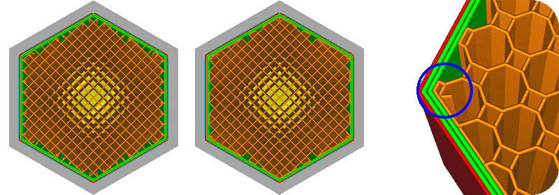
Image above: The model on the left has non-connecting Lines infill, with many start/end inwards moves. The second model uses ZigZag (connected lines), which only has two inward moves per layer. The example on the right shows an inwards move of 1.2 mm using the Octagon pattern.
Infill Start/End Preference
This setting (introduced in Cura 5.13) determines where the start and end points of the infill should be printed. There are three options available:
- Start at closest: Infill will start at the position that is the closest to the previous position.
- Start at random: Use a random position for each infill area. This prevents one segment becoming the strongest, but it does so at the cost of an additional travel move.
- End close to seam: The infill lines will be ordered so that they end as close as possible to the next wall seam. If required, an infill line will be split to provide an appropriate ending position. This helps shortening the travel move between the infill and the wall start position, which should provide a better wall seam, at the cost of adding travel moves during infill print.
Tip: Continue learning about all UltiMaker Cura custom settings. The next section is Material.