The information in this article applies to UltiMaker S series printers, including the UltiMaker S3, S5, and S7.
S series printers use two print cores in the print head. These print cores have a vertical and a horizontal offset. The vertical offset (Z direction) is set during active leveling, and the horizontal distance (X and Y direction) is stored via an XY calibration process. A correct XY calibration will ensure that the two colors or materials align well.
The print cores that are supplied with the UltiMaker S3, S5, and S7 are already calibrated. When you install a new combination, the printer will notify you via a prompt on the display. For the best results, perform the XY offset calibration before starting a dual extrusion print. This calibration only needs to be performed once for each combination; the printer stores this calibration information internally.
Requirements
For the XY calibration, the UltiMaker S series printer will run a short print with both cores, after which you are asked to select the printed lines with the best alignment. The XY calibration will take about 10 minutes.
You will need the XY calibration sheet, which is included in the accessory box. If you no longer have this sheet, you can download it here. Print this file on an A4 paper at 100% scale. You could also simply use it as a digital reference.
Note: The XY calibration sheet (v2) describes the workflow for a glass plate. The v3 version which is linked above contains more generic instructions and is more suitable for the UltiMaker S7.
Ensure two print cores and two materials are installed before starting the calibration. In combination with the Material Station, there must be at least one compatible spool preloaded for extruder 1 and one compatible spool preloaded for extruder 2.
Instructions
Perform the steps below for the UltiMaker S series XY calibration:
Note: The process for the UltiMaker S7 is a little different compared to the UltiMaker S3 and S5 due to the different build plates. See Align the grid below. The printer's display refers to a translucent sheet, but this is incorrect and will be fixed in a future firmware release.
| Start calibration |
Go to Preferences → Maintenance → Print head → Calibrate XY offset and select Start calibration. The UltiMaker S3, S5, or S7 will now print a grid pattern on the build plate. Wait until it is complete.
|
| Align the grid |
Once the build plate has cooled down, remove the build plate from the printer. See the images below for a clarification.
For the UltiMaker S3 and S5: Place the glass build plate on the XY calibration sheet. Ensure the printed grid is precisely placed onto the two rectangles on the sheet, so you can see which numbers to use for reference.
For the UltiMaker S7: Remove the flexible build plate carefully without bending it. Place the XY calibration sheet next to the build plate to use as a reference; compare the grid on the build plate with the rectangles on the sheet.
Tip: For the UltiMaker S7, you can also choose to cut out the rectangles from the calibration sheet, so it can be placed on top of the flexible build plate.
|
| Find X offset |
Find the best-aligned lines on the printed X grid and note which number corresponds to these lines. Enter this number as the X offset value on the display.
|
| Find Y offset |
Find the best-aligned lines on the printed Y grid and note which number corresponds to these lines. Enter this number as the Y offset value on the display.
|
| Complete calibration |
Complete the XY calibration and place the build plate back into the printer.
For the UltiMaker S3 and UltiMaker S5, close the build plate clamps at the front to secure the glass plate. On the UltiMaker S7, ensure that the flexible build plate is well-aligned and fully flat.
|
UltiMaker S3 and UltiMaker S5
|
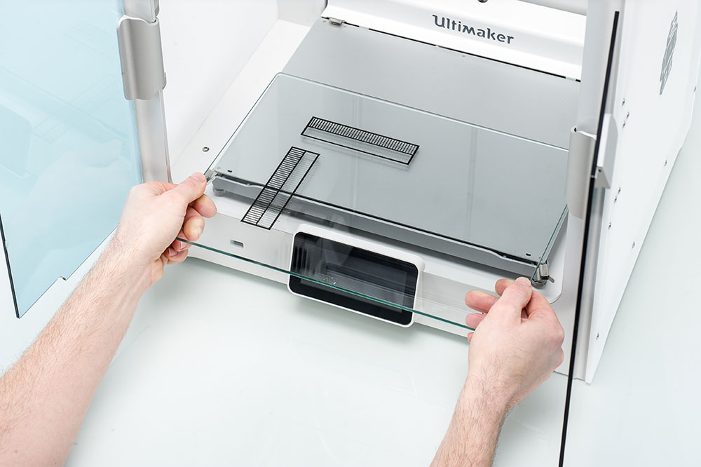
Carefully remove the glass plate | 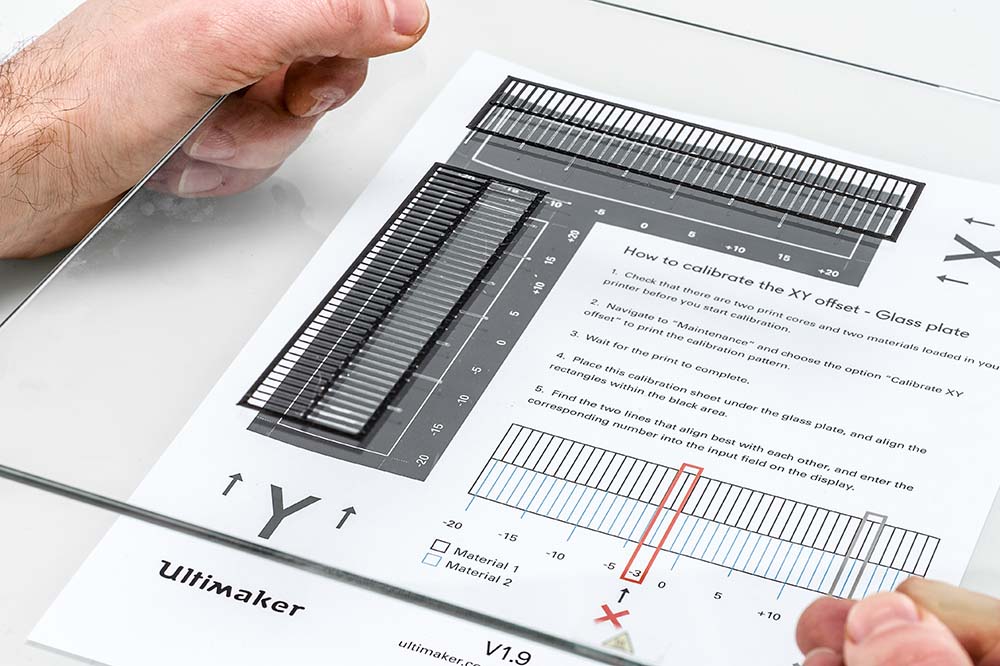
Align the grid with the XY calibration sheet |
UltiMaker S7
|
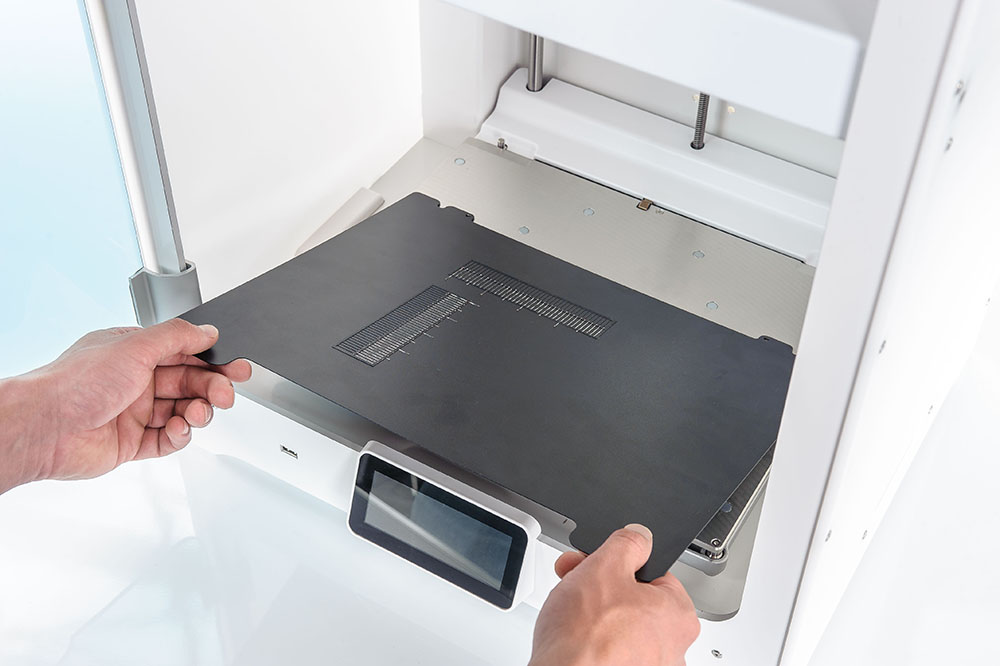
Remove the flexible build plate without detaching the XY calibration print | 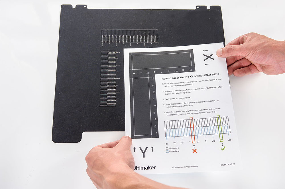
Use the XY calibration sheet as a reference |
Note: It is important that the printed XY offset print adheres well to the build plate and shows no signs of under-extrusion. If there are print quality issues that make it difficult to find the aligned lines, it is recommended to repeat the calibration print. If necessary, first relevel the build plate or clean the print cores to improve the print quality.
Tip: If you are in doubt between two values, you can also enter 0.5 values in the printer menu. For example, if you are unsure whether the lines for '1' or '2' are aligned best, enter '1.5' as the offset value.