This article describes the various speed settings in UltiMaker Cura. These settings are available when opening the Custom mode.
The settings in the Speed category control the movements of the motion system, including speed, acceleration, and jerk.
Print speed
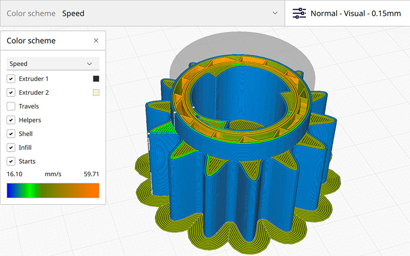
The print speed defines the speed (in mm/s) at which the print head moves while printing. Based on this setting, Ultimaker Cura calculates the extrusion flow. The print speed can be visualized per feature in the Layer view → Speed.
A higher print speed will lead to a shorter print time. Keep in mind that increasing the print speed means that you may have to increase the temperature as well to ensure the filament is properly melted.
Although you can choose one overall print speed for the complete print, it is also possible to use different print speeds for specific parts of the print:
- Infill Speed: The speed at which the infill material is printed. If the visual quality of the infill is not important, you could use a higher speed for the infill. However, keep in mind that this may affect the strength of your print.
- Wall Speed: The speed at which the object's walls will be printed. This setting controls the underlying speed settings for the inner and outer walls.
- Outer Wall Speed: The speed at which the outer walls are printed. Printing the outer wall slower usually results in a better surface finish.
- Inner Wall Speed: The speed at which the inner walls are printed.
- Top Surface Outer Wall Speed: If the object has one or more top surface layers (this can be set in the Top/Bottom section), the outer wall speed for this layer can be adjusted separately.
- Top Surface Inner Wall Speed: If the object has one or more top surface layers (this can be set in the Top/Bottom section), the inner wall speed for this layer can be adjusted separately.
- Top Surface Skin Speed: The speed of the top surface skin layers. You can set the number of top surface layers in the Top/Bottom category.
- Top/Bottom Speed: The speed at which the top and bottom layers are printed. A lower speed increases the reliability of closure on the top layers, especially for large-area prints. Additionally, slower bottom layers will increase the surface quality for overhangs.
- Support Speed: This setting configures the speed for the support structures. This is only visible if support structures are enabled. This setting controls the underlying speed settings for the different parts of the support structures.
- Support Infill Speed: The speed at which support structures are printed. The quality of the support is not usually important, so a higher value can often be used here.
- Support Interface Speed: The speed at which support roofs and floors are printed. Since these need to adhere to the model properly, they should be printed at a slower speed. The settings for roofs and floors can be adjusted separately.
Example: This image shows the visualization of the different print speeds per model feature. You can see that the outer walls are printed slower than the top layers, and the infill is even faster.
Travel Speed
This is the speed at which the print head moves when it is not extruding. A higher travel speed decreases the chance of filament oozing from the nozzle, resulting in a cleaner object. However, higher speed could also cause the nozzle to hit a previously printed part, which may damage the print due to the heated nozzle. This can be prevented by using Z-hop when retracting. Additionally, very high travel speeds may cause accuracy issues.
The travel speed for the initial layer differs from the rest of the print to ensure proper adhesion with the build plate.
Initial Layer Speed
This setting controls the speed for the initial layer, the very first layer that is put onto the build plate. By default, the speed for the initial layer is lower than for the rest of the print. This ensures that the object adheres well to the build plate. There are two sub-settings controlled by the initial layer speed, but these can be adjusted separately:
- Initial Layer Print Speed: This is the speed at which the bottom layer is printed. By default, this is slower than the regular Print Speed settings.
- Initial Layer Travel Speed: This is the speed at which the print head moves when not extruding on the very first layer. Using a lower travel speed can reduce vibrations on the build plate. If your project contains many small parts on the first layer, using a lower travel speed will reduce the risk of these parts getting pulled away from the build plate by the print head.
Skirt/Brim Speed
It is possible to adjust the speed at which the skirt or brim is printed. This setting is the same as the Initial Layer Print Speed by default, but it can also be adjusted separately. Printing the skirt or brim slower ensures that they stick better to the build plate.
Z Hop speed
This setting changes the speed for all build plate moves during the print. This includes all layer changes and Z Hops. Faster Z-hops can reduce the chance of blobs or stringing on the model (when Z Hops are enabled). However, the horizontal movements are usually limited by the maximum acceleration rates of the Z axis.
Number of Slower Layers
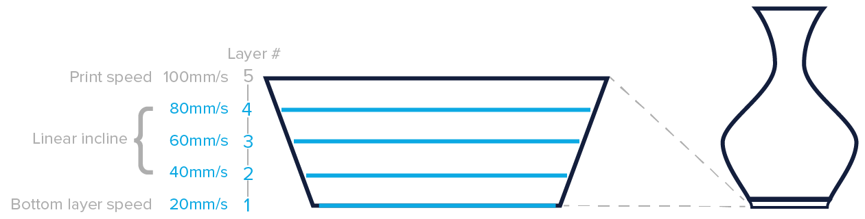
This setting defines the number of layers it takes to reach the print speed from the bottom layer of the print. The speed will incline linearly over the number of layers specified, based on the Initial Layer Speed and Print Speed. A higher value decreases the chance of warping, but can also increase the print time significantly.
If the number of slower layers is 1, then only the very first layer will be printed slowly (according to the Initial Print Speed setting). The rest of the print will use the regular Print Speed settings. This can mean a sharp transition, especially if the difference between the two speed settings is big. Gradually increasing the speed over several layers can have a positive effect on print accuracy and ensures a smoother flow rate transition. However, using more slower slayers will increase the total printing time.
Example: In the picture below, the number of slower layers is set to four. During the first four layers, the speed will increase. From layer 5 onwards, the regular print speed settings will be used.
Flow equalization ratio
Printed lines with variable line widths are printed at different speeds to ensure the flow within the nozzle changes as little as possible. The Flow Equalization Ratio determines the correction to this flow and can be adjusted to compensate the flow further when needed.
This setting is a ratio. When set to 0%, the flow rate will be adjusted, while at 100%, the print speed is adjusted. Values between 0% and 100% combine the two. If this ratio exceeds 100%, the flow rate is reduced to produce thicker lines but the speed is reduced more to compensate. Higher values have the following effects:
- Higher likelihood of more accurate line widths.
- More equal flow rates, increasing reliability.
- Some chance of ringing due to faster movements in some places.
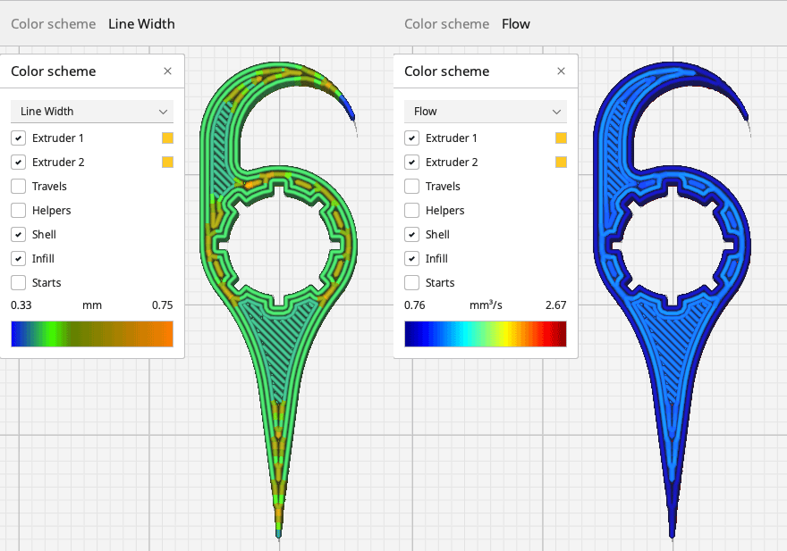
Example: This 3D model has been sliced with the default value of 110% Flow Equalization Ratio. As seen here, the line widths vary while the flow remains the same throughout the printed part.
Enable Acceleration Control
Acceleration is a very important part of printing. Just like a car, the print head needs to accelerate to get to the speeds as explained above. The acceleration reduces the speeds set in the firmware, making the print a little slower, but more accurate. Disable the setting to get the maximum acceleration.
When enabled, the acceleration settings for each part of the print can be adjusted separately. The biggest impact is on the outer parts of the printed model. Reduce the acceleration for the walls to reduce ringing (especially the outer walls) and for the top and bottom layers to increase watertightness.
Enable Jerk Control
Jerk defines the speed at which the print head can go through corners. When the print head changes direction, it would theoretically have to come to a full stop, which is not desirable for the print quality. Instead, Marlin allows for an instantaneous change in the velocity vector in each corner. Jerk is the magnitude of this change. Disable the setting to use the default jerk settings in the firmware.
Note: As this is a Marlin-based feature, the jerk settings will be ignored by every printer using a different firmware type.
Adjusting the jerk settings to higher values can have the following effects:
- Reduced print time because the print head slows down less.
- Less chance of blobs forming on the corners due to slow speeds.
- Increased vibrations can cause ringing on the print's outer surface.
- Extremely high values can cause the print head to miss steps and lead to layer shifts.
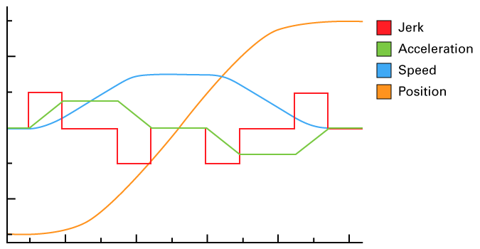
This is a theoretical image that shows the difference between speed, acceleration, and jerk.
Tip: Continue learning about all UltiMaker Cura custom settings. The next section is Travel.