The TFM coupler is the white part in the UltiMaker 2+ Connect hot end. The coupler is a consumable item that wears over time and slowly changes shape on the inside due to heat and pressure in the hot end. Eventually, this will cause friction to the material that has to pass through, which causes under-extrusion.
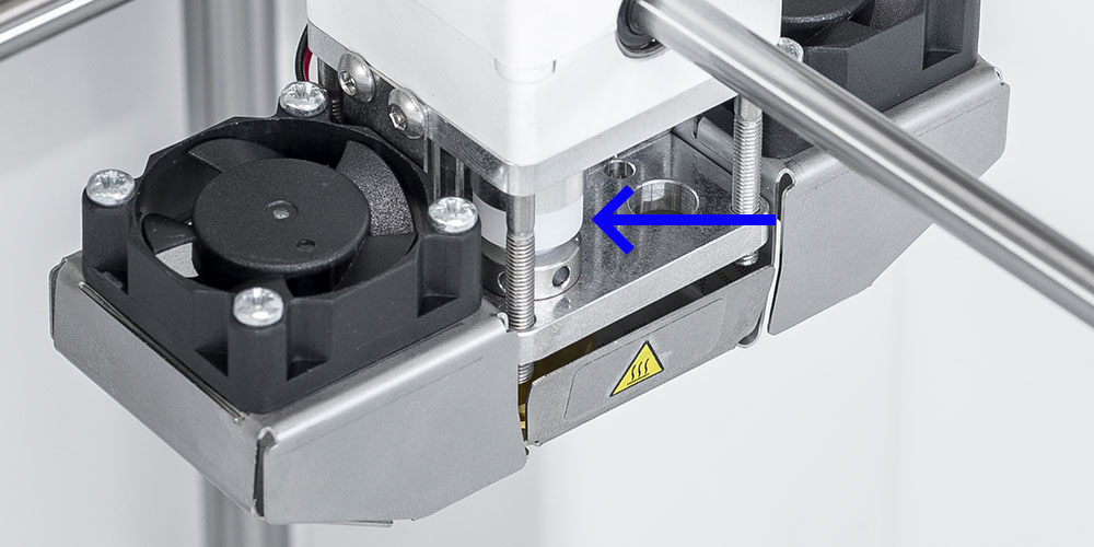
If you are experiencing extrusion problems with your UltiMaker 2+ Connect, especially after many printing hours, it is recommended to check the TFM coupler. If it shows clear signs of wear, replace it to improve your printing results.
This page explains how to disassemble the print head to reach this component.
Tip: You can also download these instructions as a PDF guide.
Requirements and info
|
Part(s)
|
1x 2278 - TFM isolator coupler
|
|---|
|
Tool(s)
|
- 2.0 mm hex screwdriver (a torque screwdriver (0.5 Nm) is recommended)
- 2.5 mm hex key
- Print head calibration aid
- Blue tape (recommended)
- Nozzle alignment tool (recommended)
|
|---|
|
Time
|
7 minutes
|
|---|
|
Difficulty level
|
2 - Accessible
|
|---|
Tip: The STL file of the nozzle alignment tool can be downloaded at the bottom of this page.
Notes before you start
- Clean the hot end with a cold pull before starting this procedure to remove all material residue from the inside of the hot end parts. This makes disassembly of these parts easier.
- Ensure the nozzle has completely cooled down to avoid a risk of burns.
- Unload the filament from the print head and turn off the printer before you start the disassembly process.
- While disassembling the print head, make sure to keep all small parts, such as the bolts, somewhere safe so they don't get lost.
Disassembly instructions
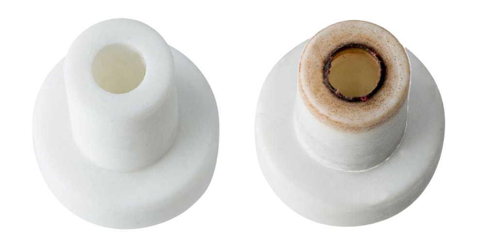
This image shows the difference between a new and a used coupler. If the edge at the bottom looks burnt, frayed, or deformed, replace the coupler with a new one.
Reassembly instructions
Finished!
After replacing the TFM coupler, you can now turn on the printer again, reload your material, and run a quick test print.
Tip: This process may have caused a small change in the height of the print head and thereby the position of the nozzle. Level the build plate to ensure that your first layer adheres properly to the glass build plate.
Downloads