The TFM coupler is a consumable part inside the print head. This can wear over time due to the heat and pressure in the Ultimaker 2+ hot end. Depending on the used print temperatures, it is recommended to check this part every 400 - 800 printing hours. Replace it when the coupler looks damaged, burnt, or deformed.
Caution: Unload the material, turn off the printer using the power switch at the back, and disconnect the power cable before starting this procedure. Ensure the nozzle has cooled down completely.
Note: These instructions are for the Ultimaker 2+ and Ultimaker 2 Extended+. The instructions for the Ultimaker 2, Ultimaker 2 Go, and Ultimaker 2 Extended are similar.
Instructions
Checking and replacing the TFM coupler requires partial disassembly of the print head. Follow the steps
Requirements and info
|
Part(s)
|
1x 2278 - TFM isolator coupler
(alternatives for Ultimaker 2 series include 1309 and 1364)
|
|
Tool(s)
|
2 mm hex key or screwdriver
Print head calibration aid
Blue tape (recommended)
Nozzle alignment tool (recommended)
|
|
Time
|
7 minutes
|
|
Difficulty level
|
2 - Accessible
|
Disassembly
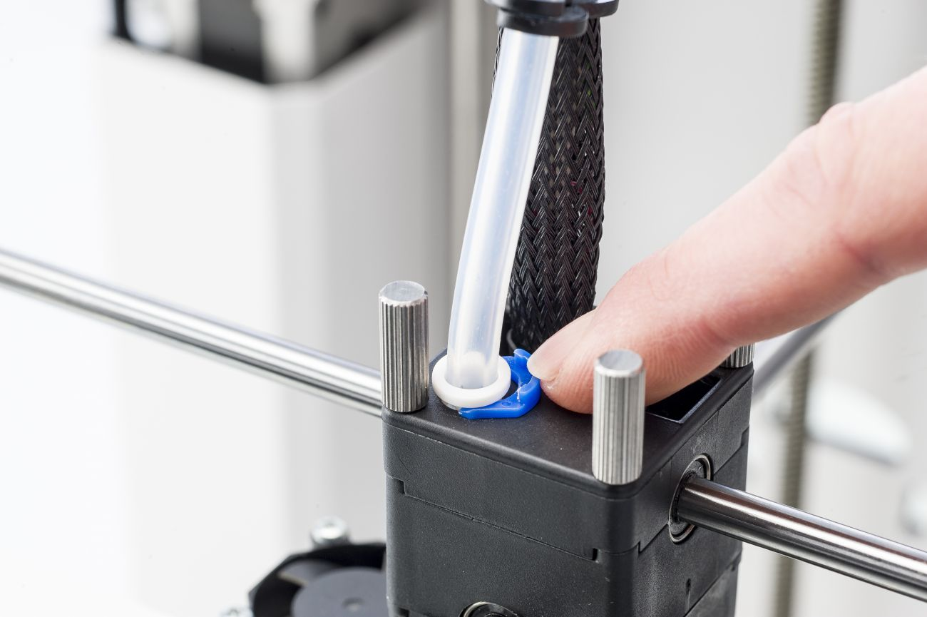 | 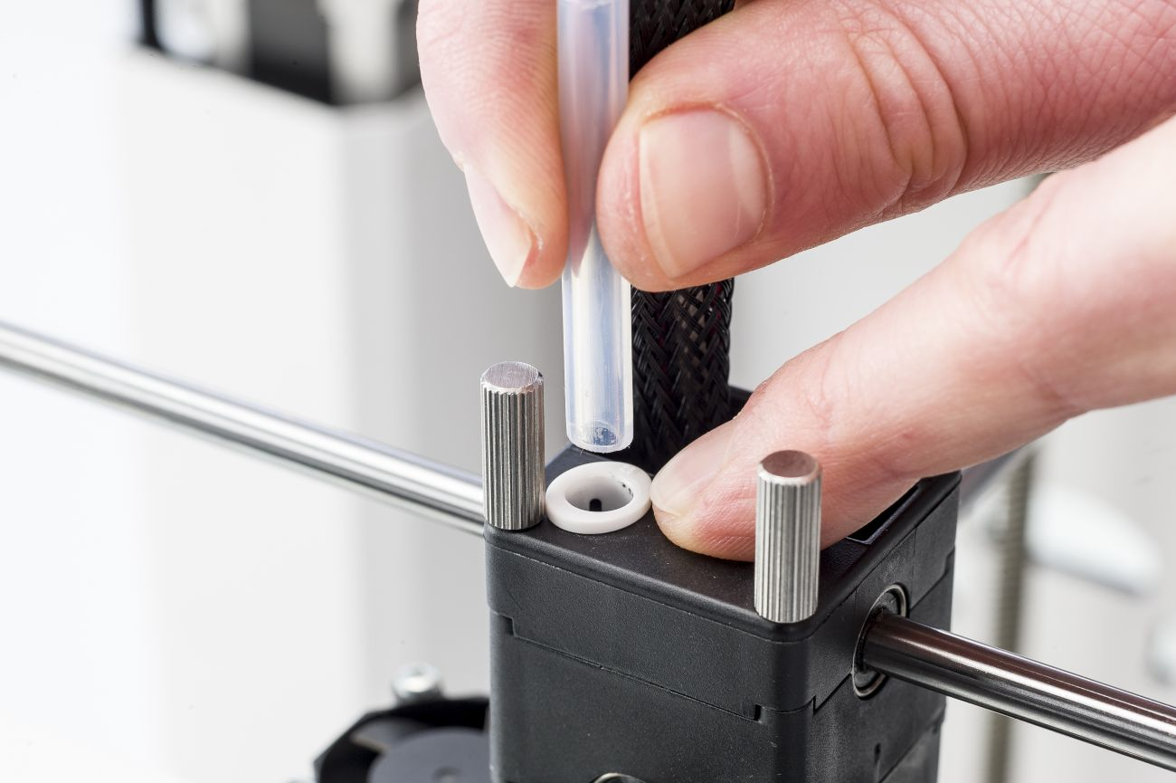 |
| 1. Remove the clamp clip | 2. Remove the Bowden tube |
| Manually place the print head in the front left corner for easier access. Remove the clamp clip from around the tube coupling collet. | Press down on the tube coupling collet while pulling the Bowden tube out of the print head. |
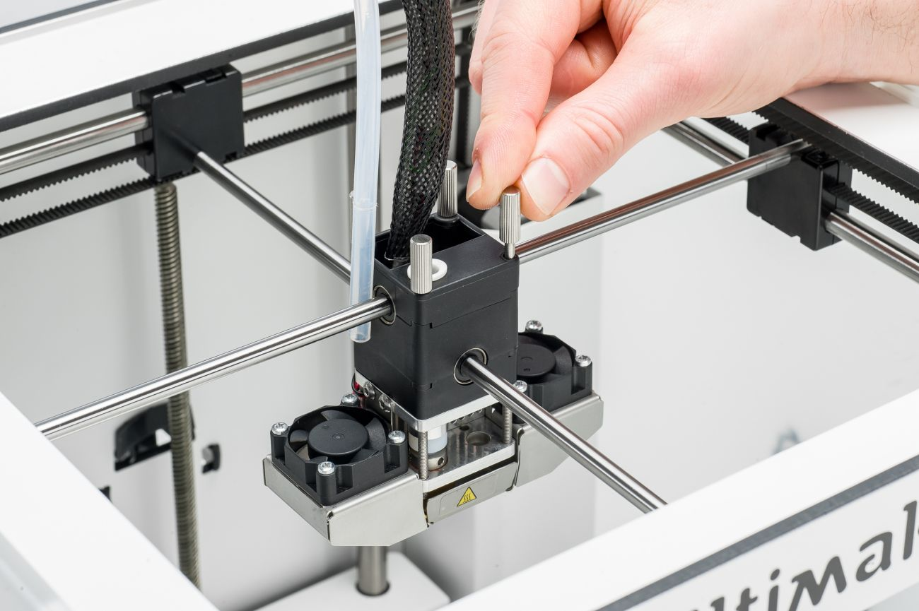 | 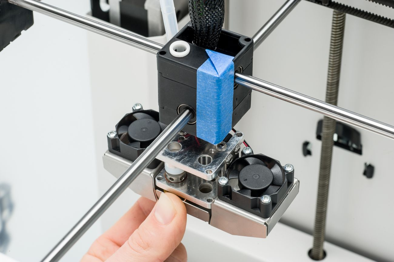 |
| 3. Remove the long screws | 4. Separate the print head |
| Loosen and remove the four long screws that go through the print head housing. | Place some blue tape around the print head housing to keep the parts together (recommended). Gently move down the bottom part of the print head. |
 |  |
| 5. Remove the fan bracket | 6. Remove the aluminum plate |
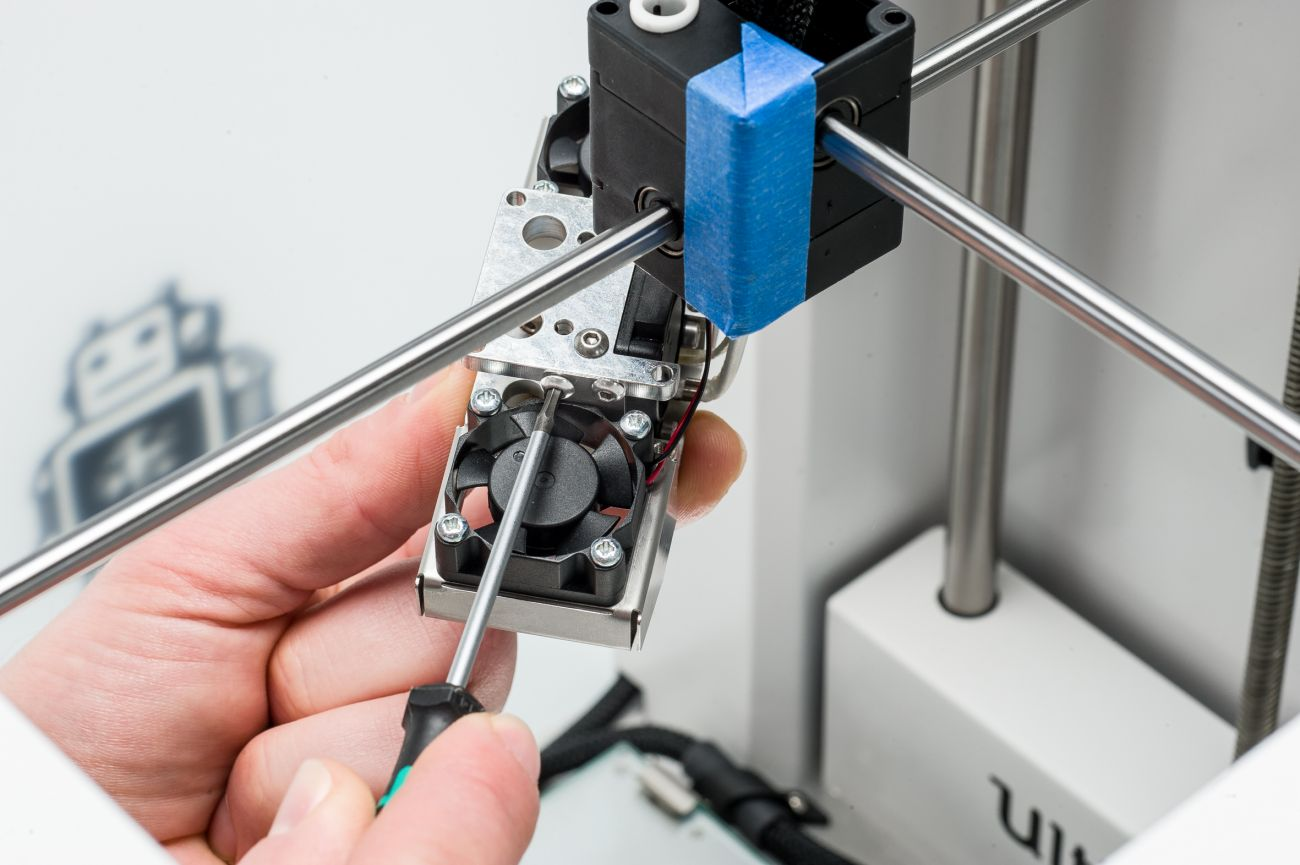
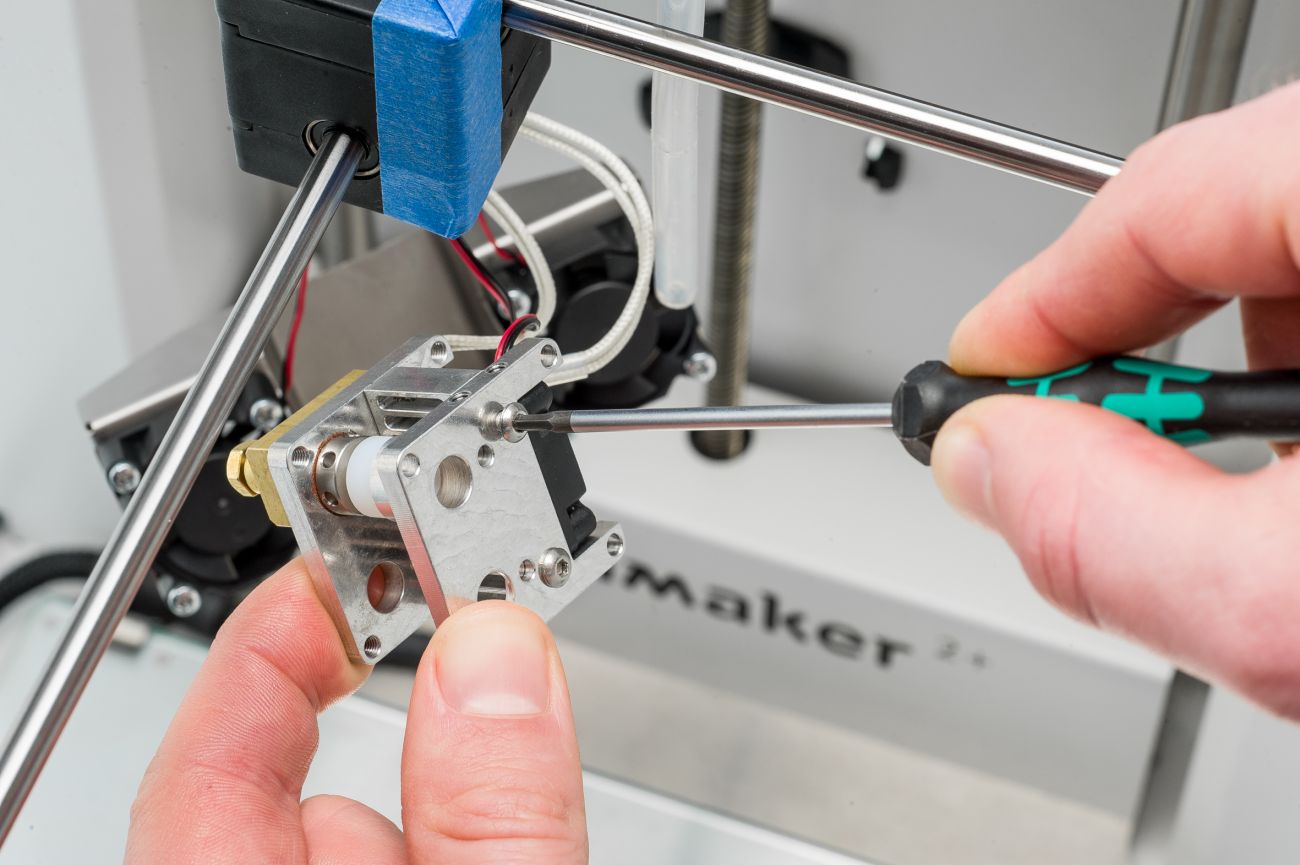
| Use the 2 mm hex key or screwdriver to loosen and remove the two small M3x4 bolts on either side of the print head that secure the fan bracket. | Use the 2 mm hex key or screwdriver to remove the two M3x10 bolts from the top aluminum plate. Take this plate off the hot end assembly. |
 |  |
| 7. Remove spacer and coupler | 8. Inspect the TFM coupler |
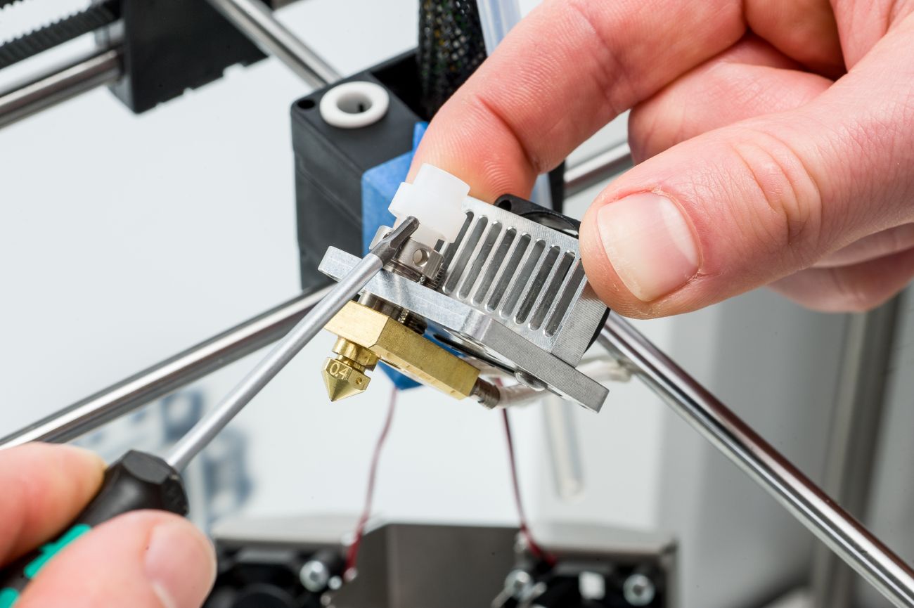
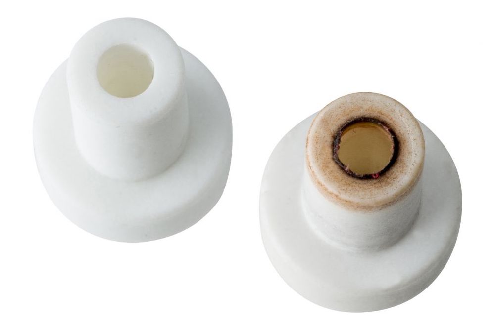
| Take the metal spacer off the TFM coupler and place it aside. Next, take the TFM coupler out of the hot end isolator. If necessary, use the screwdriver to pry it out. | Check the bottom of the coupler. This image shows the difference between a new and a used coupler. If the edge at the bottom looks burnt, frayed, or deformed, replace the coupler with a new one. |
Re-assembly
Finished!
After replacing the TFM coupler, you can now turn on the printer again, reload your material, and run a quick test print.
Tip: This process may have caused a small change in the height of the print head and thereby the position of the nozzle. Level the build plate to ensure that your first layer adheres properly to the glass build plate.