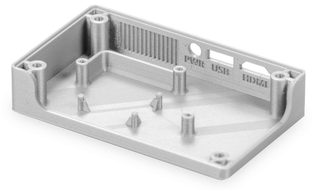
Designing parts to print with engineering materials can be more challenging than using materials such as PLA. Some engineering materials have a higher tendency to shrink, causing warping or the distortion of certain features. To combat this, there are ways to optimize the design of your model.
A well-designed model that follows these guidelines and uses UltiMaker Cura's recommended profiles will help to improve print reliability.
Example features
The diagram below shows some useful features that work well for 3D printed parts:
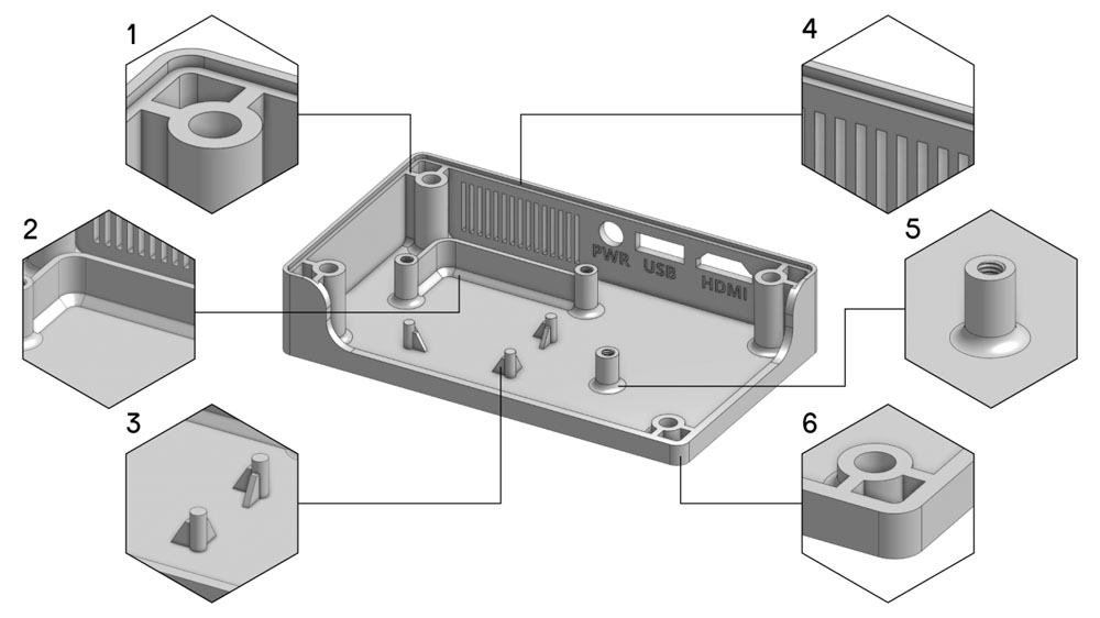
- Rib. A rib is a special type of extruded feature that adds material of a specified thickness in a specified direction between the contour and an existing part. Ribs are fundamental features for enhancing the structural integrity of your 3D printed parts. Connecting the part to a wall strengthens the construction. It also supports the part from the bottom surface.
- Chamfer. A chamfer is a beveled edge between two (near) perpendicular surfaces in the model. Using chamfers (often 45°) as a transition instead of sharp corners reduces stress and increases the strength of the connection.
- Gusset. A gusset is a small triangular extra surface between extruded features and the bottom surface (or wall, when used for horizontal features). Gussets help to support features with more surface contact like a rib. However, they do not connect to another feature or wall, but it tapers off as the Z height increases.
- Wall thickness. Generally, designs with a uniform and consistent wall thickness decrease the chance of warping or shrinkage. A consistent wall thickness will improve the overall stability of the printed part, and it avoids weak points in the design and extrusion changes.
- Fillet. A fillet is a rounded corner between two surfaces. Similar to chamfers, fillets reduce stress in areas where two surfaces meet and strengthen the connection. Additionally, the smooth transition will often help to improve the visual quality of the print.
- Rounded corners. Using rounded corners instead of sharp (90°) transitions help distribute the stress in the material more evenly throughout the model. This enhances the overall print quality and reduces the risk of weak points or fractures. Sharp corners can cause sudden changes in speed, acceleration, and the extrusion rate, which leads to visual quality issues such as ringing / ghosting.
Tip: You can look at these features in more detail and see how these are sliced using the Cura profiles. Download the STL here.
Design recommendations
The table below shows the design recommendations for some challenging UltiMaker materials:

Fine features: X = Y = 1.5 mm for features where Z ≤ 3 cm. For example, a pin feature of 3 cm should have a minimum diameter of 1.5 mm. For a taller feature, the diameter should be increased.